In this article: We replace the factory Fender stereo on a 2018 MK7.5 GTI with Sony's latest lineup of Mobile ES speakers. We'll walk through things like wiring, tapping into the head unit for the signal, along with building a custom sub enclosure and false floor.
Difficulty: Hard
Time Spent: ~18 hours
The Fender system that comes in Volkswagen's MK7 and MK7.5 GTI is a nice upgrade over the standard stereo. Among other things, it includes an upgraded subwoofer in the trunk that rounds out the system nicely, upgraded speakers and tweeters along with a dedicated amplifier. Even although it probably performs above and beyond 90% of people would expect out of a car stereo today, I wouldn't consider it a high performance system and we wanted a little more out of this GTI. Sony gave us the opportunity to give it just that!
In this article, we'll cover the custom system we installed in our 2018 MK7.5 GTI, including replacing all of the factory Fender drivers with Sony's latest Mobile ES lineup, and powered by their XM-GS6DSP 6/5 channel amp. This project was a great opportunity for us to ‘up' the clarity and quality of the GTI's stereo, add some more bump in the trunk. But it was also a great time to put Sony's Mobile ES speakers to the test. We previously did an unboxing and first look review of Sony's Mobile ES speakers, but hadn't put them in an amplified system yet. Win, win, win for us. And we weren't disappointed. That said, this install is not for the faint of heart. It requires programming, lots of wiring, tuning and customization in order for this install to be worth it. Although the outcome was great and the Sony system sounded phenomenal, I would not recommend this particular install for the average DIYer with the Fender and amplified systems from the factory. Here's a few photo of the vehicle that we did this installation in. You can also follow the owner on instagram @turbo222gti. Images are taken by @manualimage.
Exterior Photos


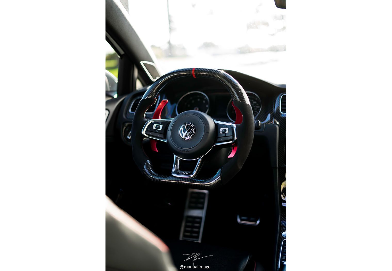
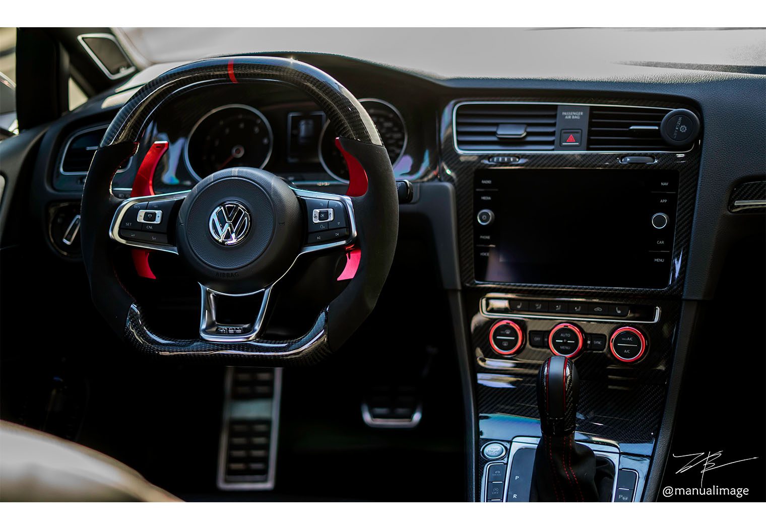
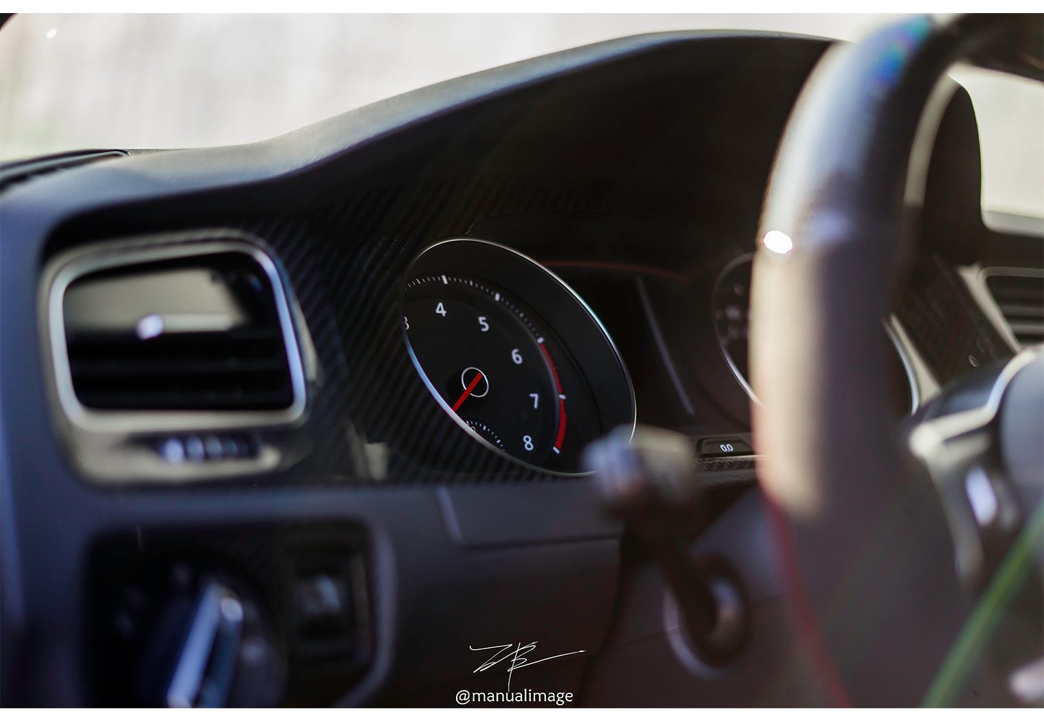
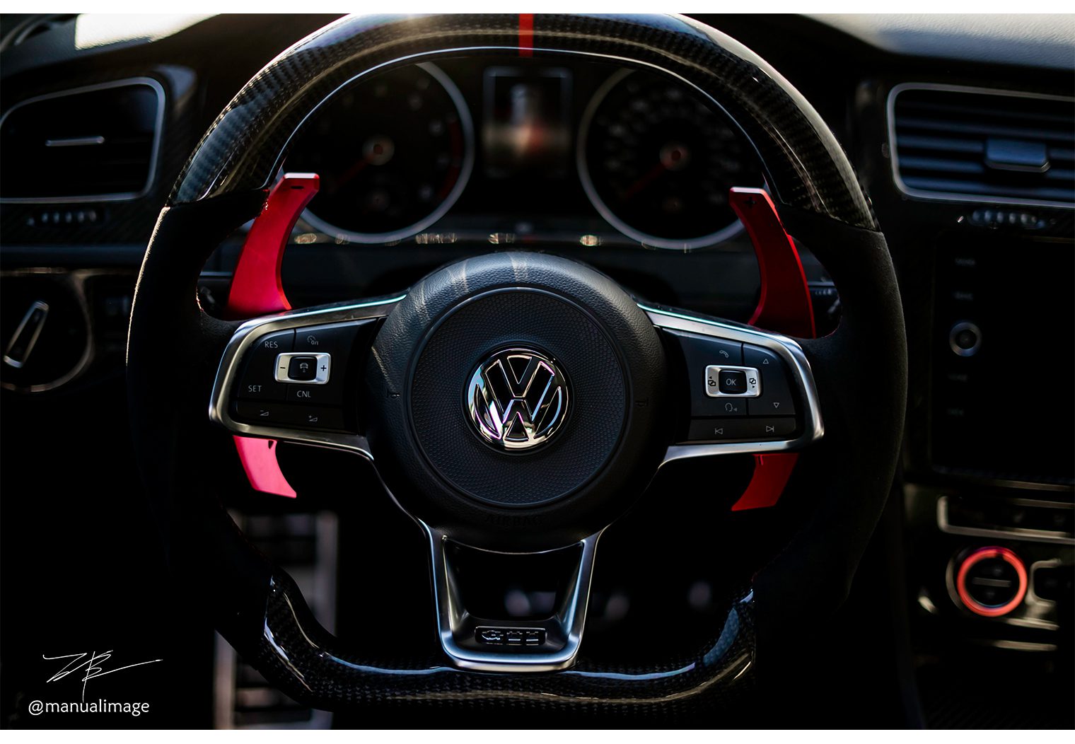
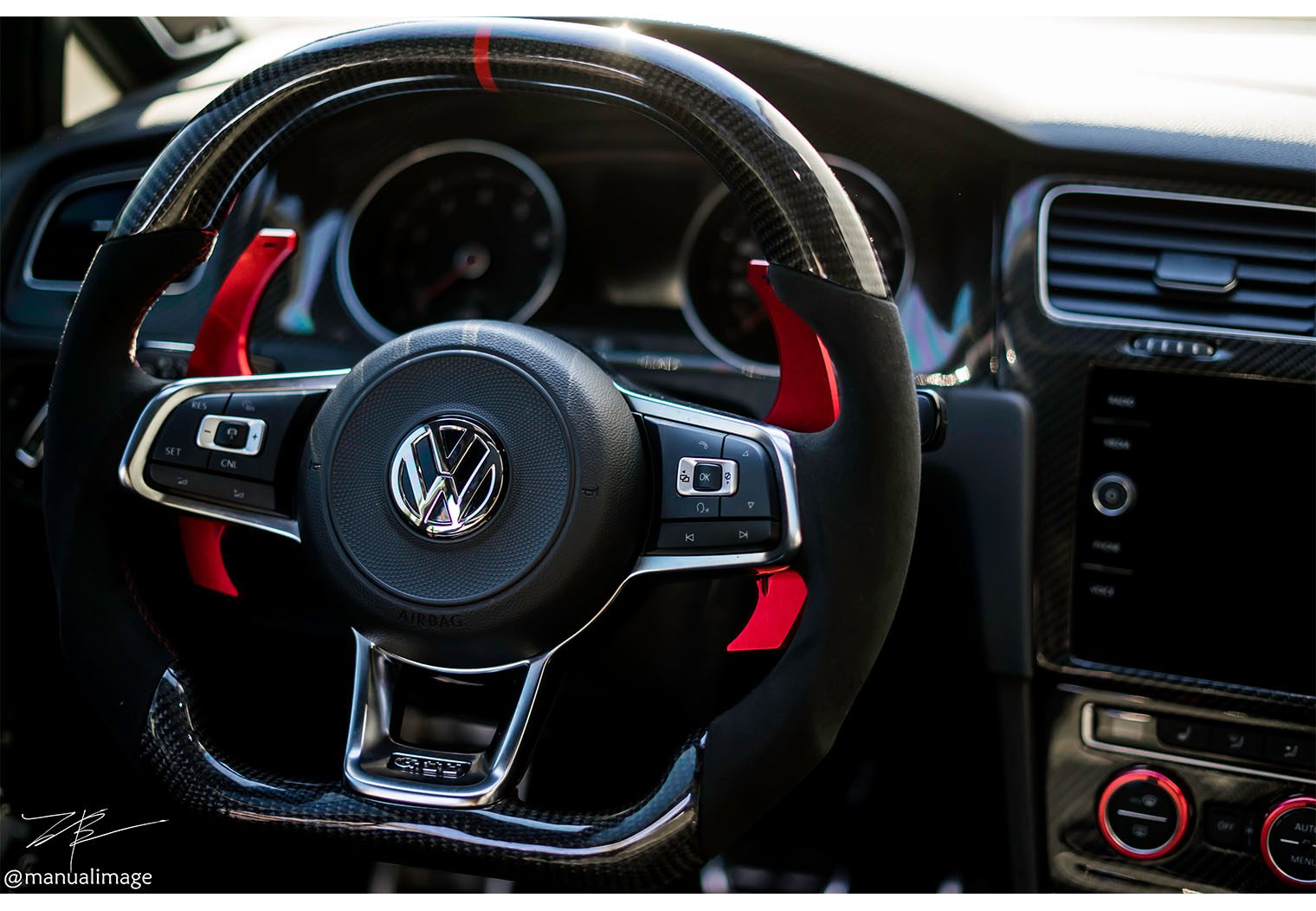
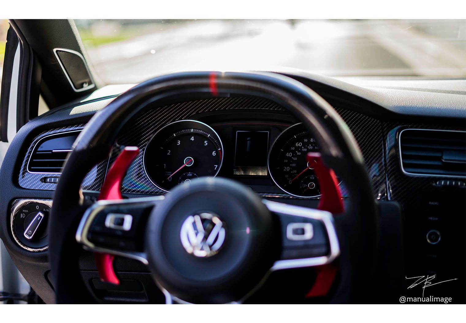
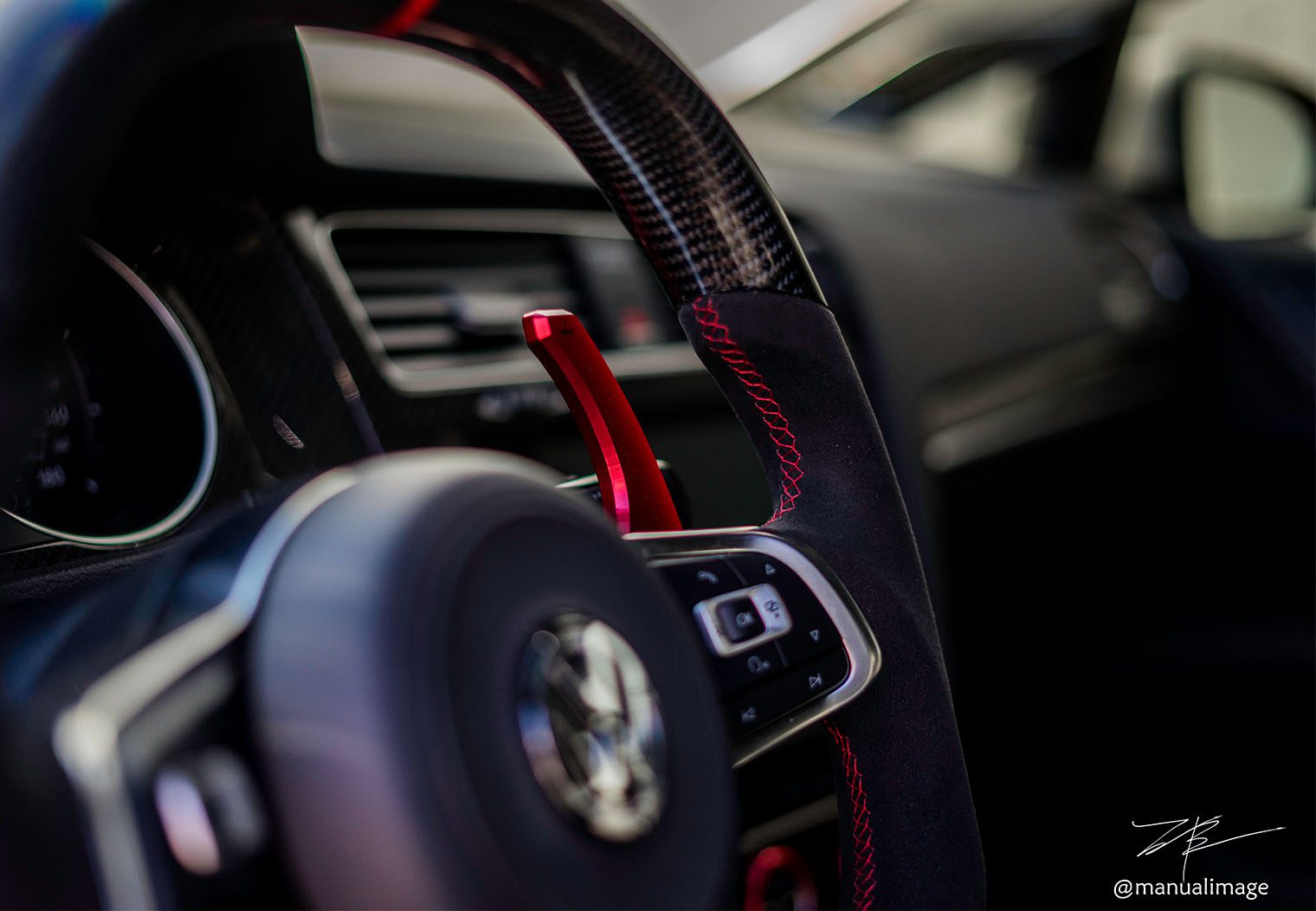
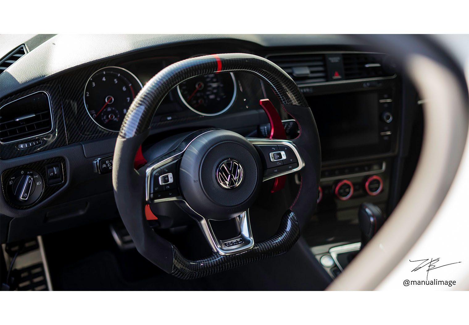
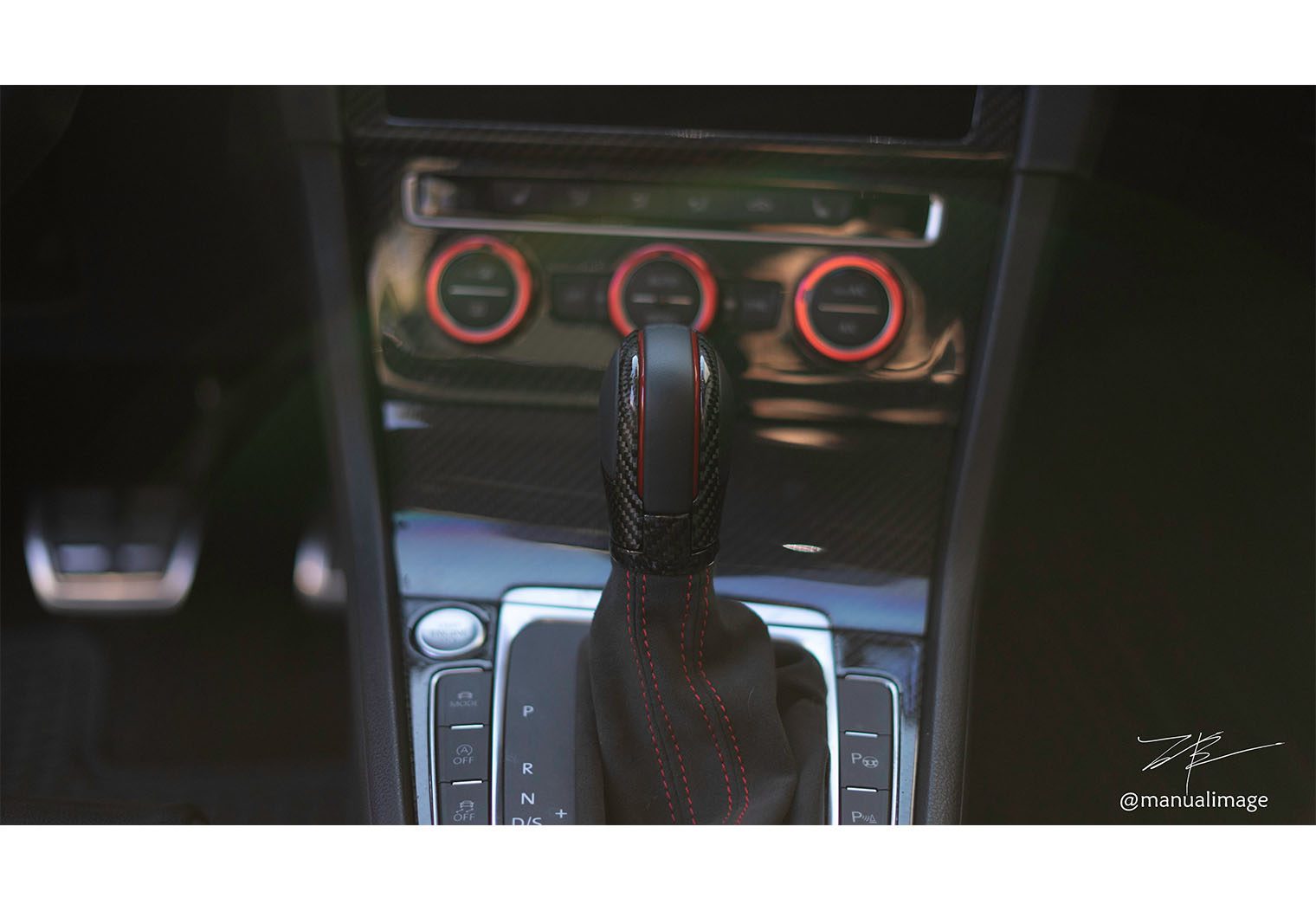
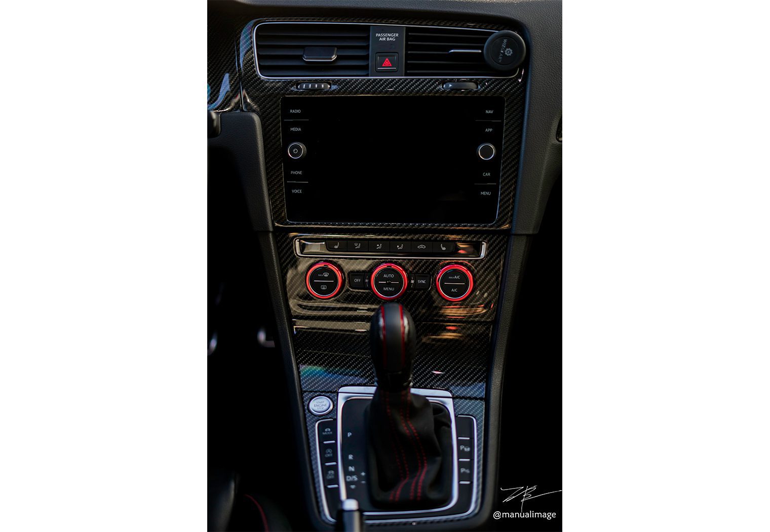
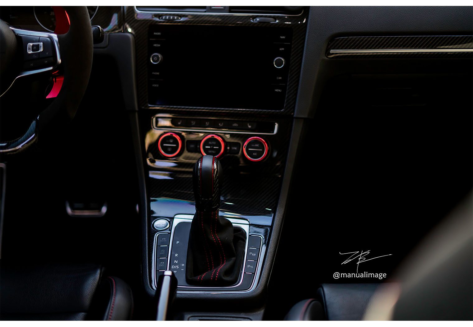
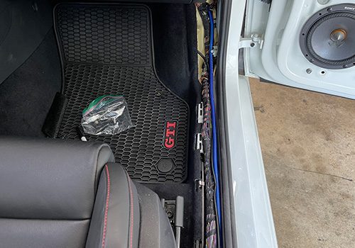
Interior Photos
Project Goals
Since there's quite a few ways to assemble, plan and install a new stereo in a GTI I always like to outline some of the driving factors that led to the decisions which ultimately determine the build. So here's a few things to point out before getting into the build:
- We wanted more volume and bass but also stealth. The more integrated the upgraded components were, the better.
- The Sony Mobile ES lineup was pre-decided as the choice of products for this installation so we built the system around these components and requirements.
- Retaining the factory head unit was a must.
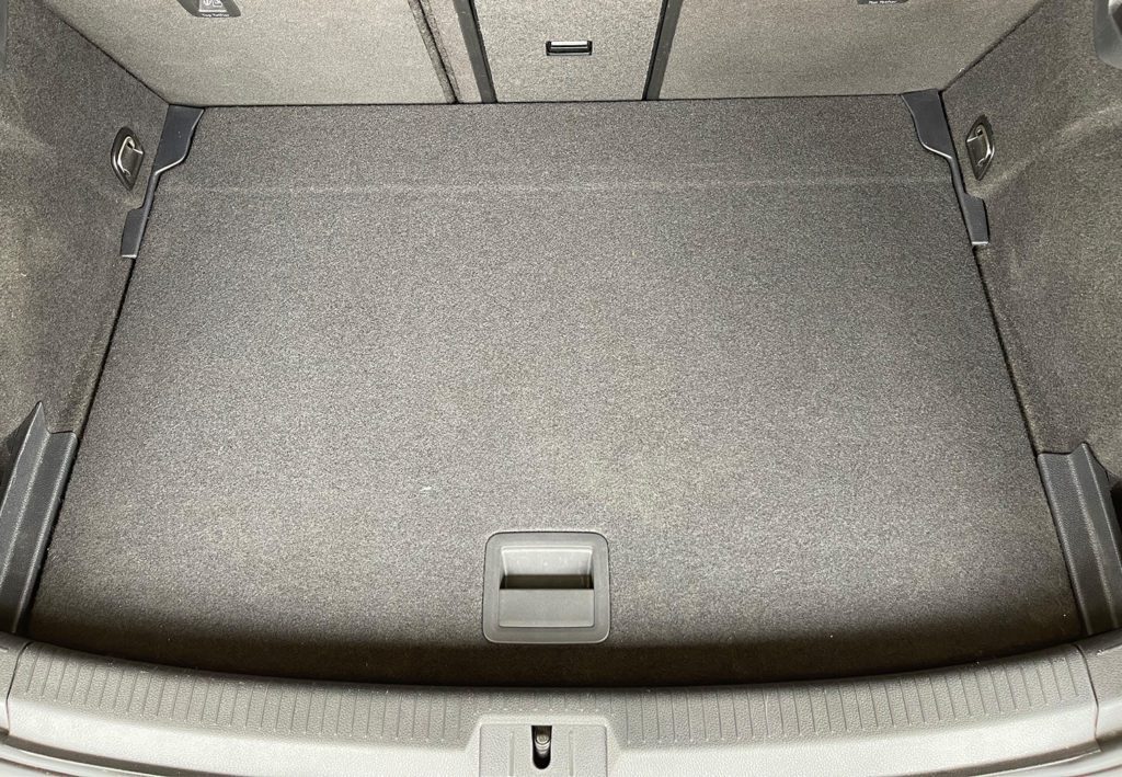
- Untouched trunk space was a must.
Products That We Chose for This Installation
Here's a list of the key parts and products we chose for this installation. There's always more minor stuff, but these are the core components.
- Sony XS-162ES (2) – Sony's 6.5″ component system for both the front and rear doors along with tweeters.
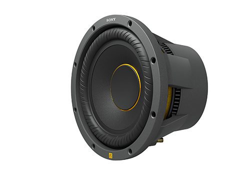
- Sony XS-W104ES – Sony's matching 10″ Mobile ES subwoofer.
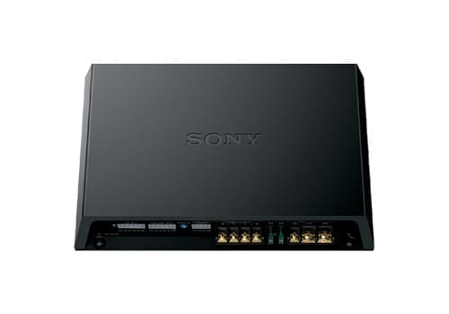
- Sony XM-GS6DSP – 6/5 Channel Class D Amplifier with DSP that very adequately powered all four component speakers and the subwoofer.
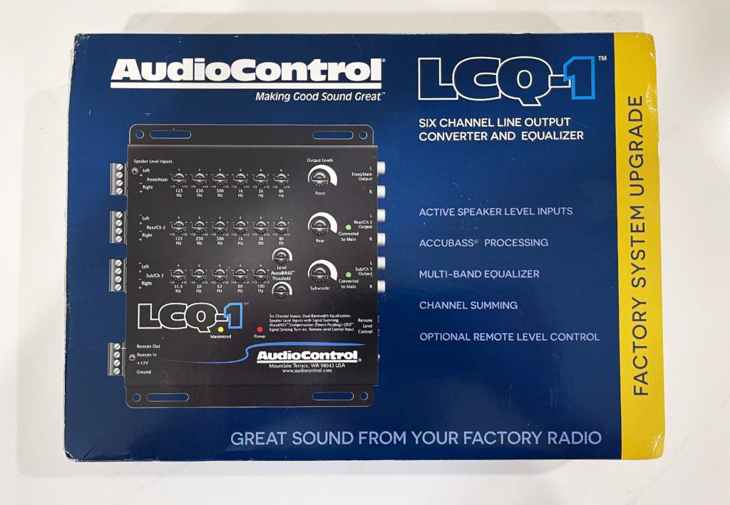
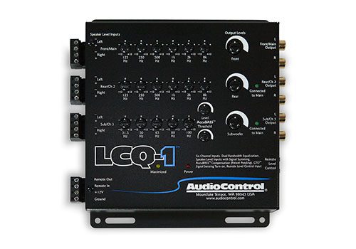
- AudioControl LCQ-1 – Line output converter & equalizer to convert and tune the signal from the factory head unit to the aftermarket amplifier input.
- SoundSkins Pro Door Kit SSPRO-1 – Sound dampening kit for the trunk space.
- 4′ x 8′ sheet of MDF – For the subwoofer enclosure and the artificial floor and amplifier mount.
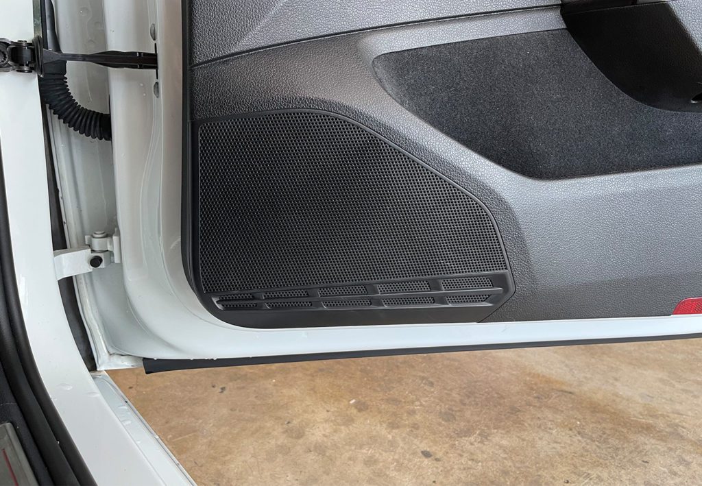
Speaker Installation
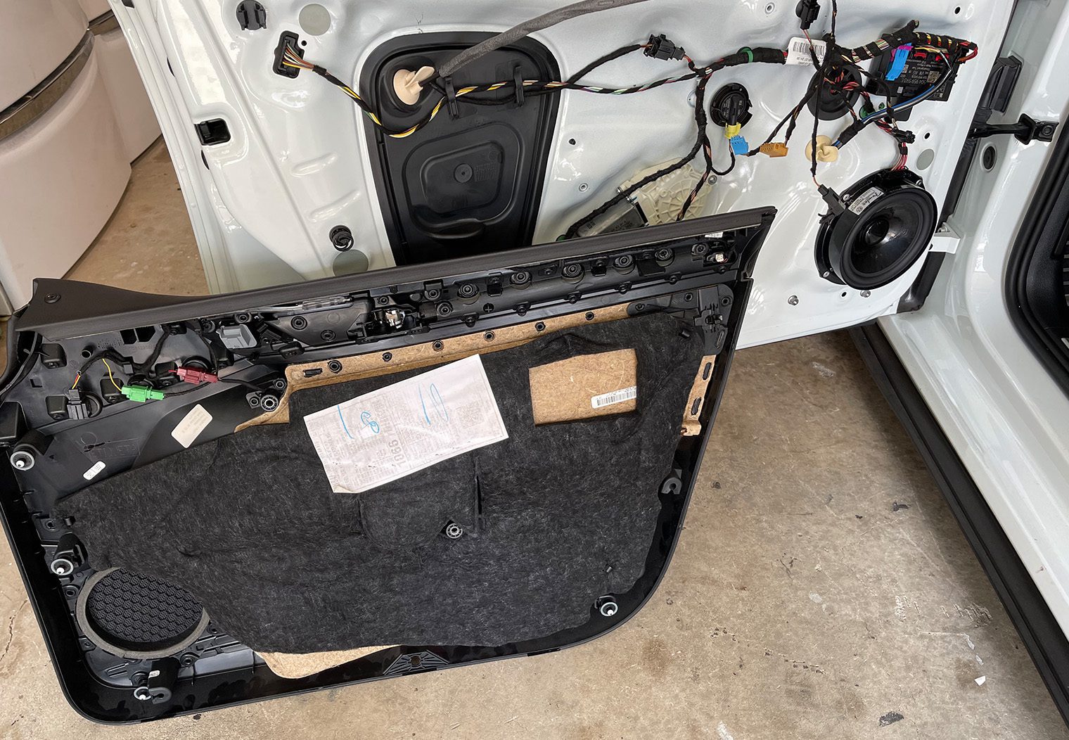
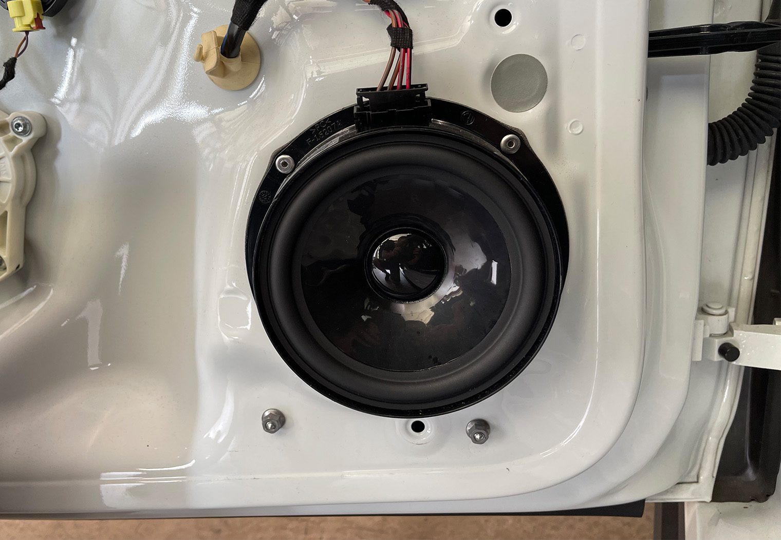
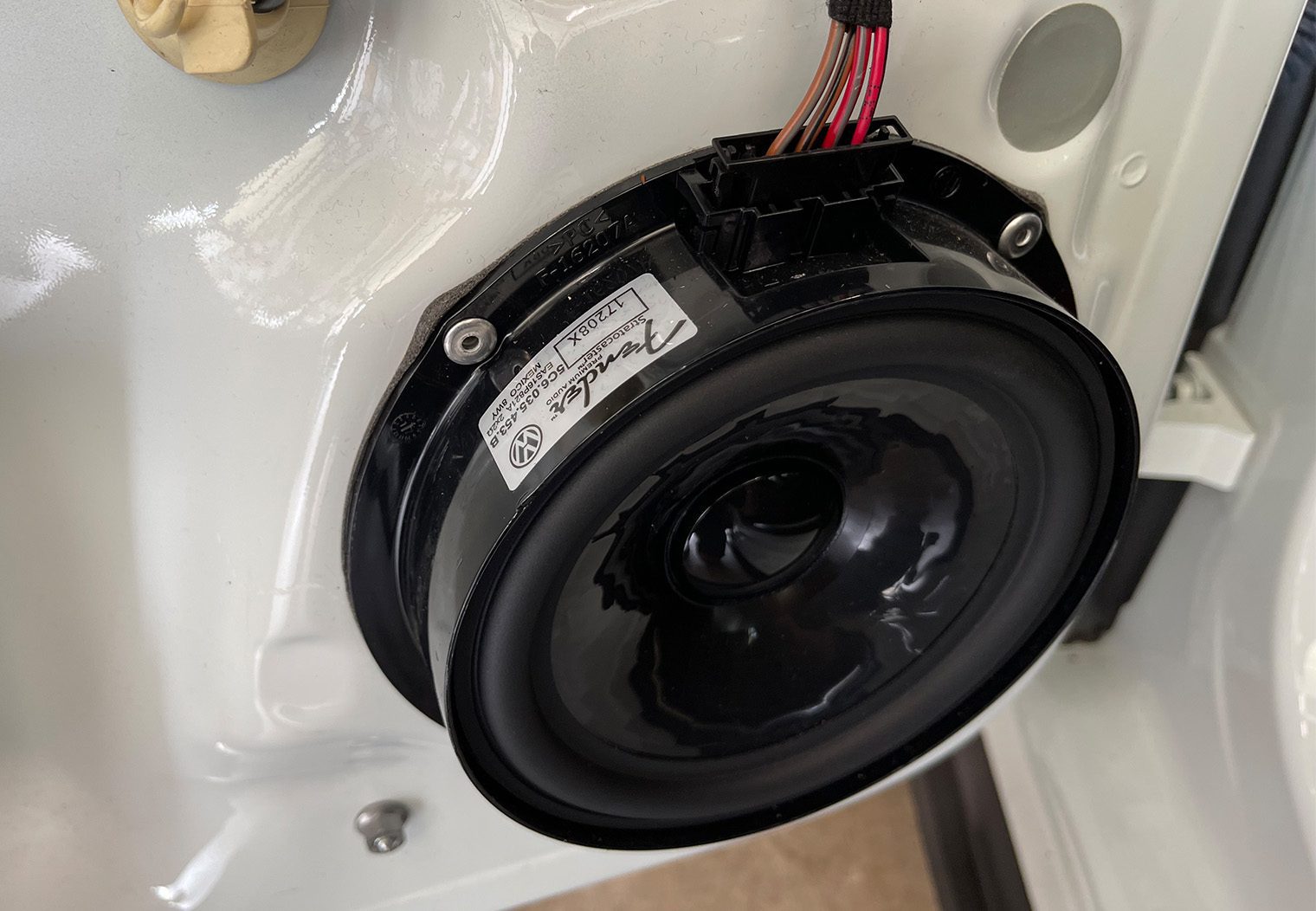
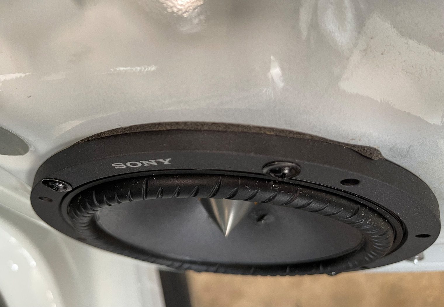
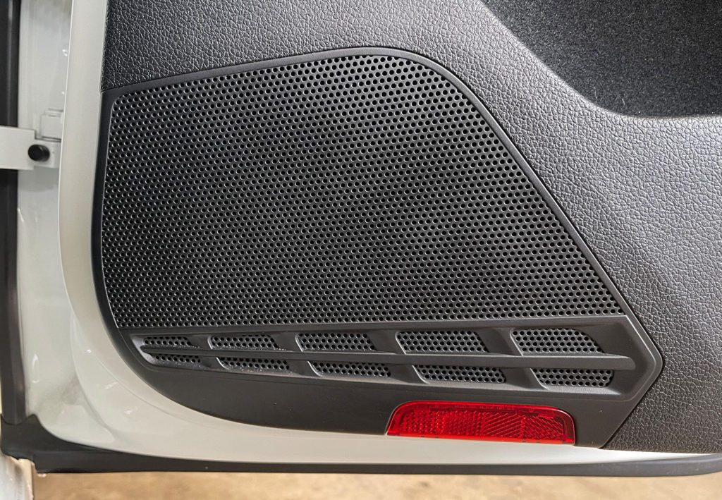
We replaced the four in-door speakers and tweeters with Sony's 6.5″ components. The Fender system comes with 6.5″ component speakers all around, built into ~2″ spacers/adapters that are riveted into the door panel.
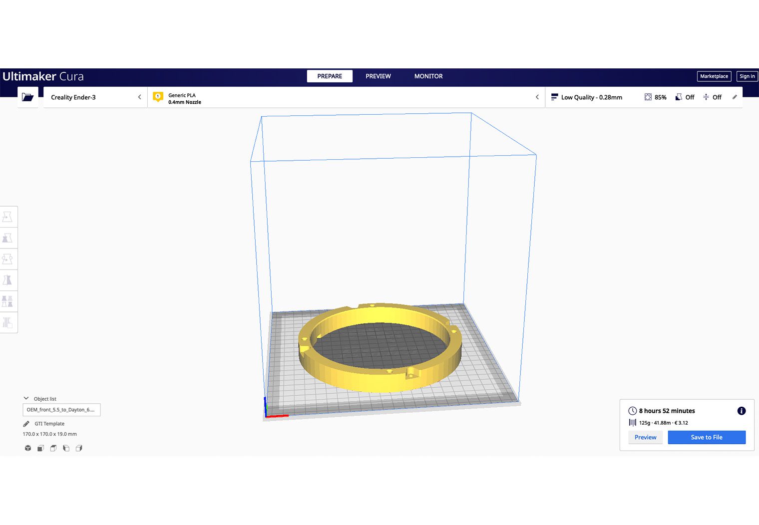
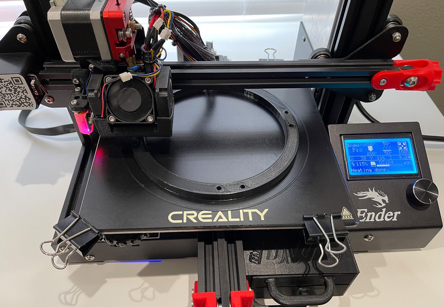
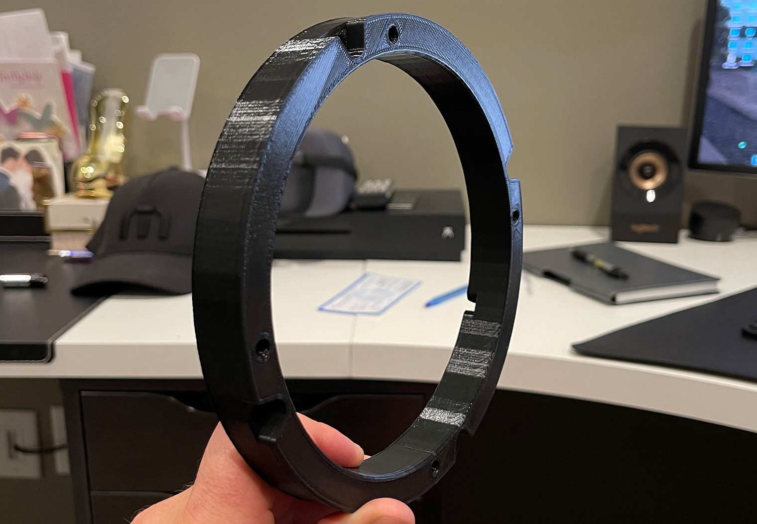
Before the installation, we began with prepping by finding some adapting spacers that I could print out with our 3D printer. I wasn't exactly sure the depth I had to play with behind the OEM speakers in the door panel so it was a safe bet. I found a 3D print design (props engrkris) that would actually take the OEM rivet hole pattern and convert it into the new aftermarket speakers with about a 1″ spacer to pull it out of the door panel a bit in case there was clearance issues with the window or other components inside the door panel. They came out pretty nice actually. The files had optional speaker wire slots built into the design so that you could wire through the adapter to the back of the speaker. This is important if you're not looking to modify the factory harness int he door.
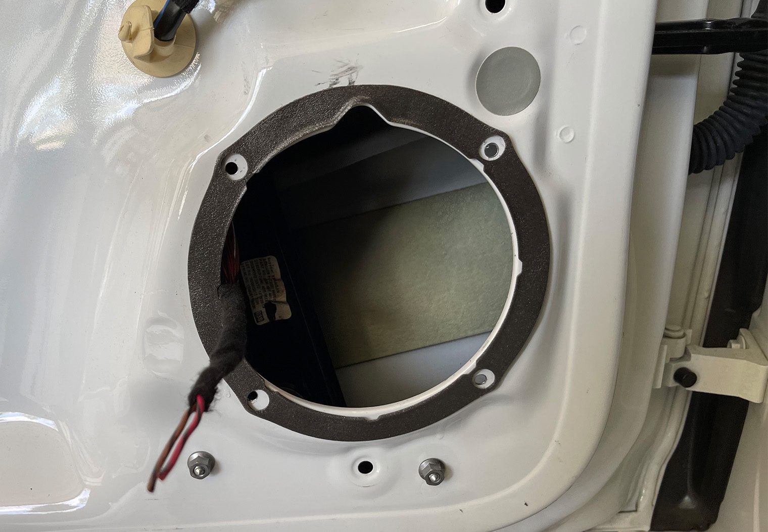
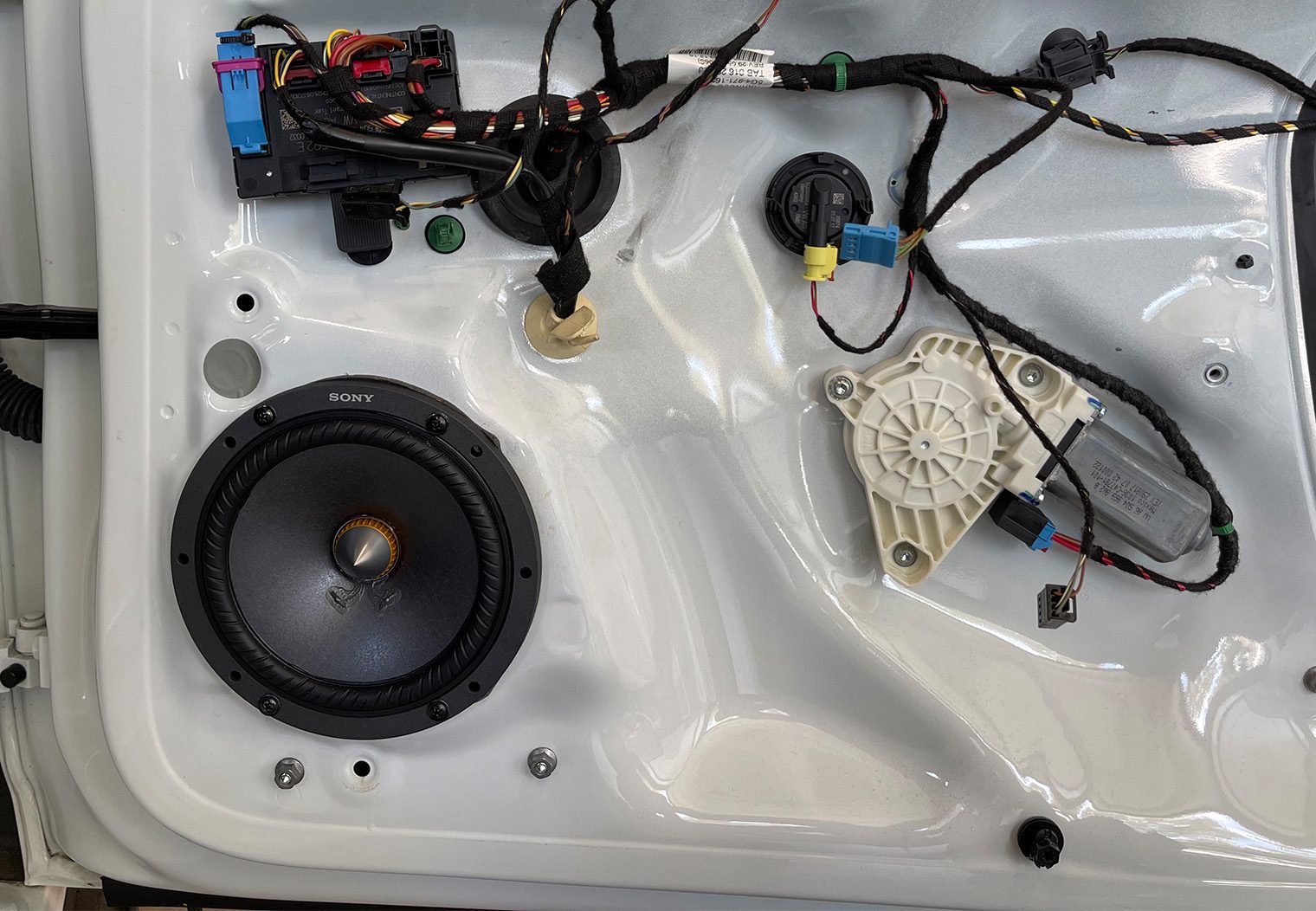
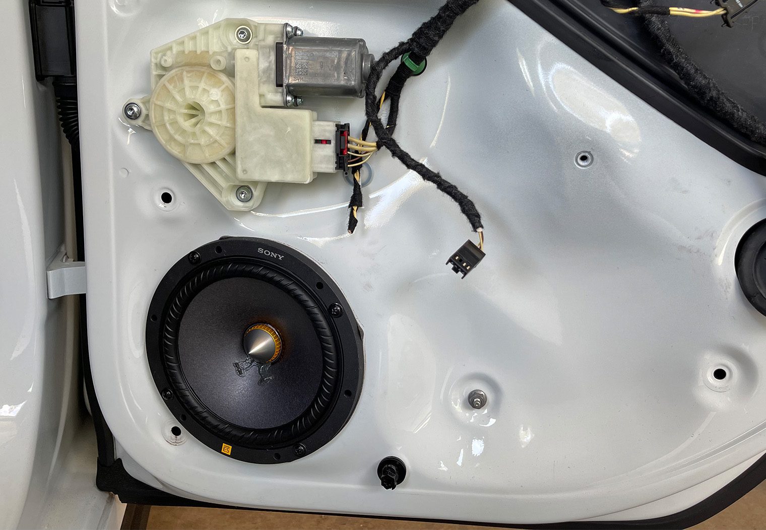
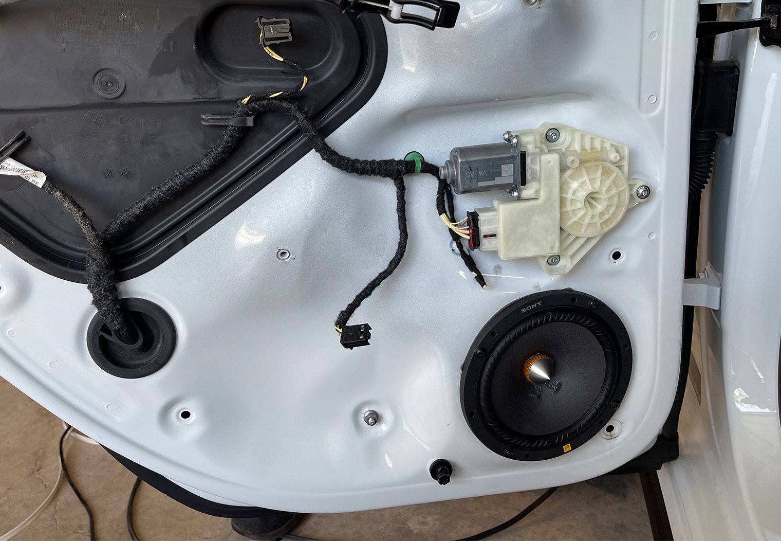
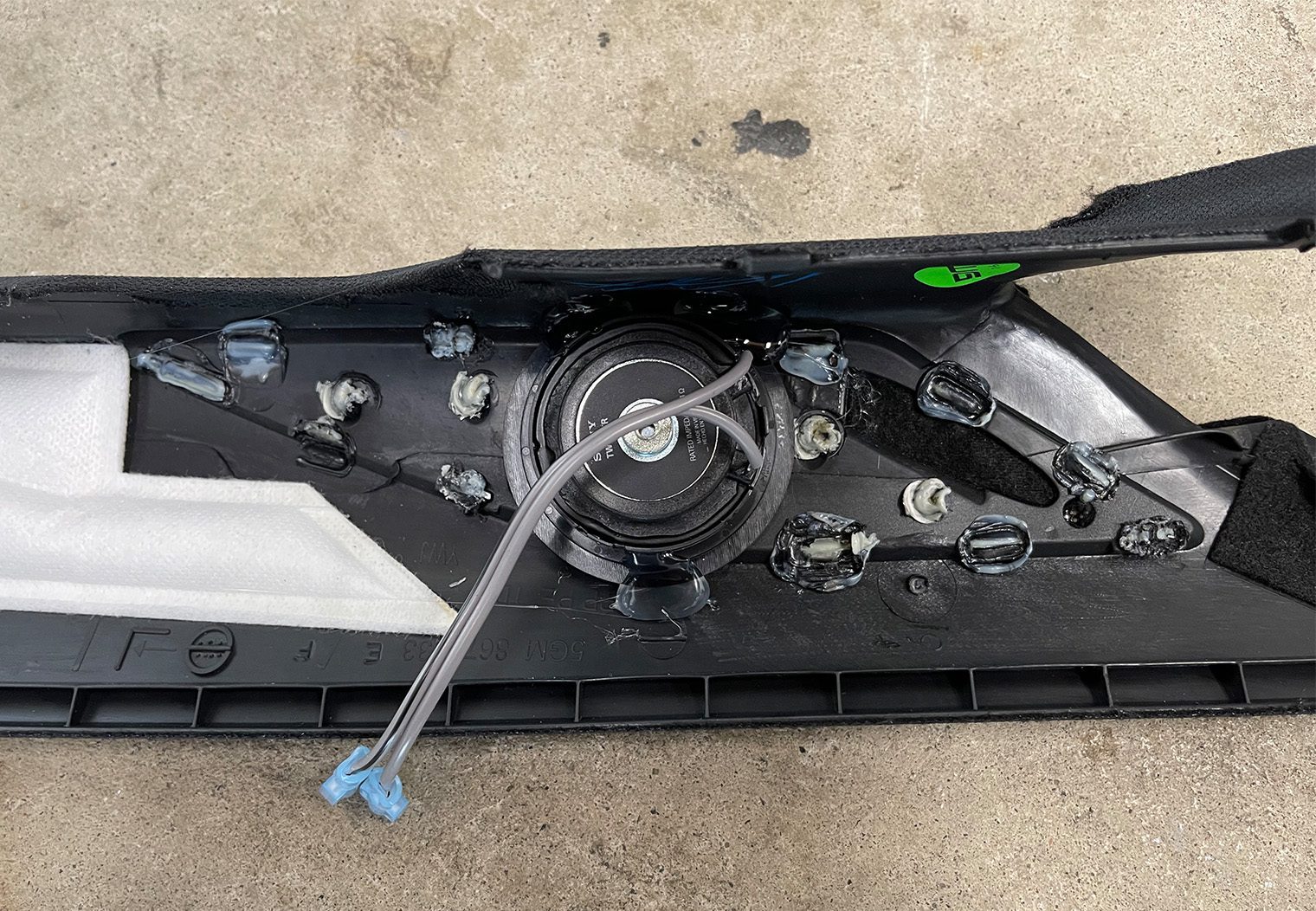
But the XS-162ES ended up being shallow than the OEM Fenders, and after some testing – rolling the windows up and down a few times while we had the new Sonys placed in the door – I realized that the spacers weren't needed at all. So we mounted the speakers directly to the panel, using some self-tapping screws along with some sealing material between the speaker and the door panel. Here's some photos of the OEM speaker before and after removing them.
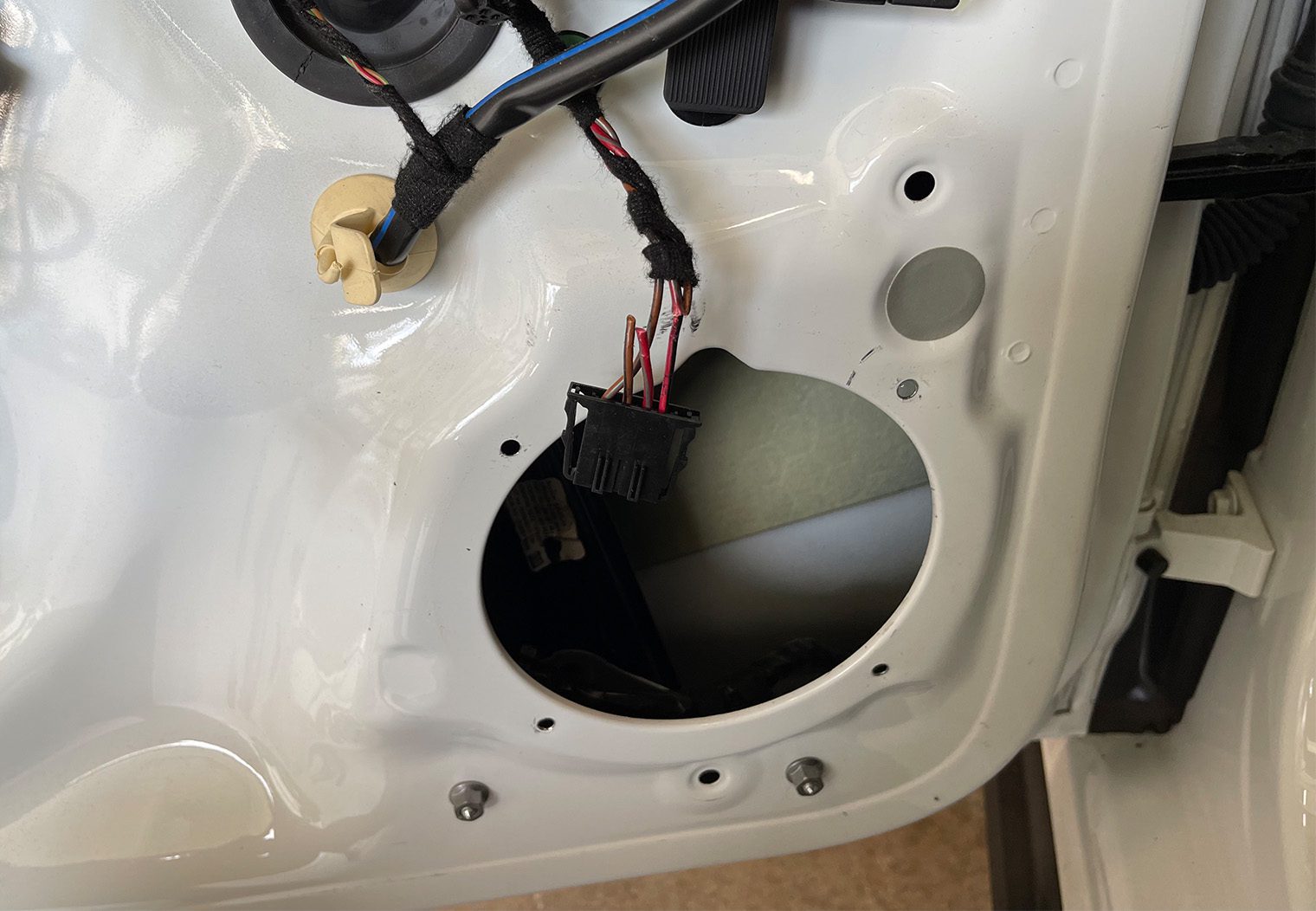
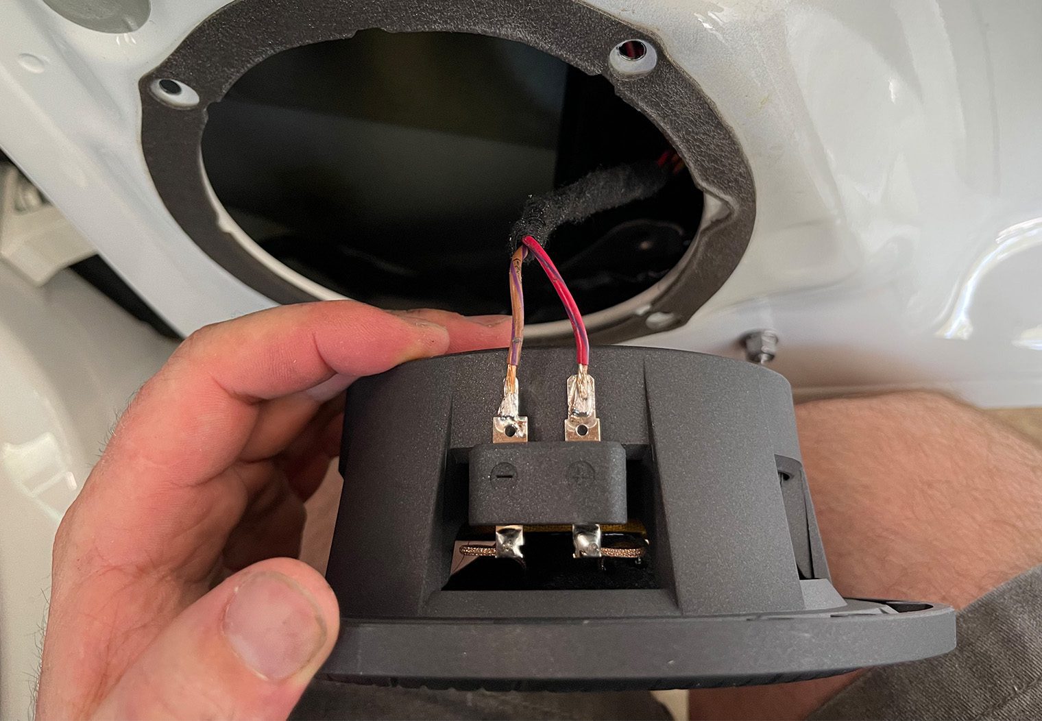
And for wiring, we removed the OEM clip, located the wire colors in the harness from within the door panel, and soldered them directly to the leads on the speaker to make for a clean, sealed speaker mounting. I've seen many of the guys on the forums who add spacers just to get the wire to the back side of the speaker. But pulling it directly from the wire harness that runs along the inner portion of the door panel was actually simple, and gave me plenty of wire length to strip and solder them directly to the speaker leads. I did this for all four speakers.
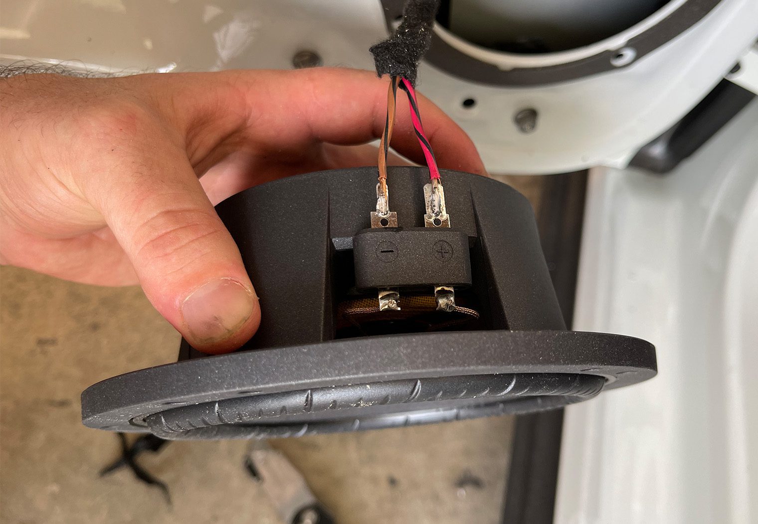
When wiring up the new speakers there's two points to call out that aren't ‘plug and play', so to speak.
- The OEM front door speakers require four separate wires (two positive, two negative). The new Sony speaker (and most of the aftermarket choices) only require two. I chose the inner two for my wiring (brown/black and red/black). But as long as you match positive and negative to the proper crossover output when you go to wire up the crossovers, you'll be fine.
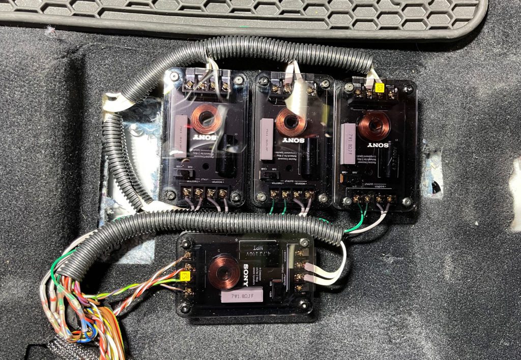
- The rear door speaker wires are tough to determine. They were all-white with nothing that would indicate polarity. So what I ended up doing was wiring up the rear door speakers without any regard to polarity, and then used a 9V battery using the good ole 9V battery polarity test when I was wiring up the crossovers. This ensured that the polarity was correct at the crossover outputs. Here's a look at the speaker wiring.
| Speaker | Color | Harness Pin # | Pin / Wire Size | Same Color All The Way? |
| Front Left Tweeter – | Brown / Yellow | 11 | S 1.0 | Y |
| Front Left Tweeter + | Red / Yellow | 12 | S 1.0 | Y |
| Front Right Tweeter – | Brown / Red | 6 | S 1.0 | Y |
| Front Right Tweeter + | Green / White | 18 | S 1.0 | Y |
| Front Left Mid 1 – | Brown / Black | 3 | M 1.5 | Y |
| Front Left Mid 1 + | Red / Black | 15 | M 1.5 | Y |
| Front Left Mid 2 – | Brown / Gray | 13 | S 1.5 | Y |
| Front Left Mid 2 + | Red / Gray | 14 | S 1.5 | Y |
| Front Right Mid 1 – | Brown / Purple | 9 | S 1.5 | Y |
| Front Right Mid 1 + | Red / Purple | 21 | S 1.5 | Y |
| Front Right Mid 2 – | Brown / Green | 10 | S 1.5 | Y |
| Front Right Mid 2 + | Red / Green | 22 | S 1.5 | Y |
| Subwoofer 1 – | Brown | 4 | M 2.5 | Y |
| Subwoofer 1 + | White | 16 | M 2.5 | Y |
| Subwoofer 2 – | Brown / Yellow | 5 | M 2.5 | Y |
| Subwoofer 2 + | White / Yellow | 17 | M 2.5 | Y |
| Rear Left Tweeter – | Brown / Blue | 32 | XS 0.75 | becomes #7 white after door harness |
| Rear Left Tweeter + | Green / Yellow | 31 | XS 0.75 | becomes #6 white after door harness |
| Rear Left Mid – | Brown / White | 7 | S 1.5 | becomes #4 white after door harness |
| Rear Left Mid + | Red / White | 19 | S 1.5 | becomes #3 white after door harness |
| Rear Right Tweeter – | Brown / Black | 34 | XS 0.75 | becomes #7 white after door harness |
| Rear Right Tweeter + | Blue / Black | 33 | XS 0.75 | becomes #6 white after door harness |
| Rear Right Mid – | Brown / Green | 8 | S 1.5 | becomes #4 white after door harness |
| Rear Right Mid + | Blue / Yellow | 20 | S 1.5 | becomes #3 white after door harness |
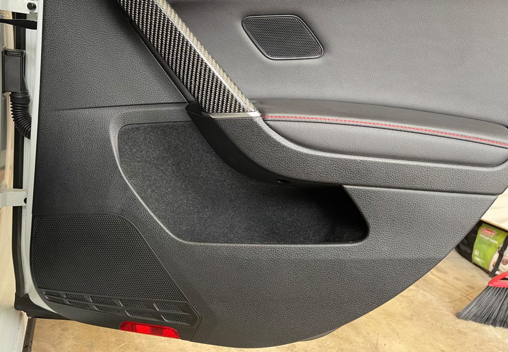
To mount the new components to the door panel, like I mentioned earlier, I chose some self tapping screws. I easily salvaged the OEM speaker sealing outer ring and mounted them directly to the panel without the ring. With the depth of these new Sonys, I didn't have to worry about the window or any clearance issues behind the speaker. Here's some photos of the end result
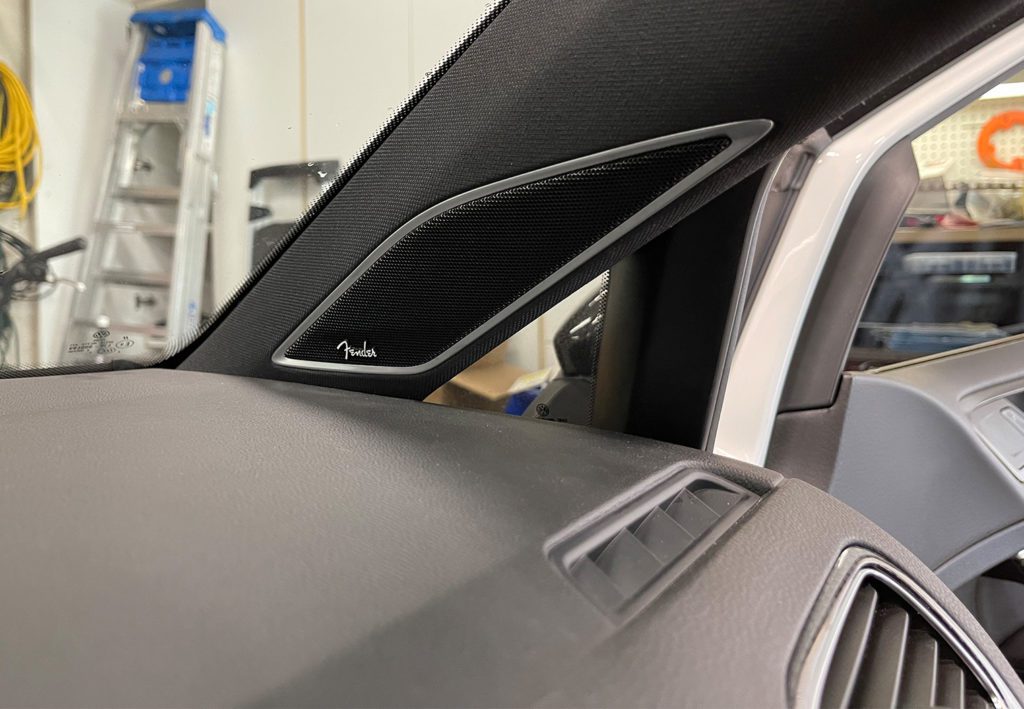
Tweeter Installation
The tweeter installation was fairly straight forward. The most challenging part was removing the front A Pillar trim panels. These are held into place by two stage clips. This article from the guys at AutoInstruct will do a good job at helping you navigate how to remove them. It's not an easy task and I would recommend you taking your time. The two stage clips are what prevent your side airbag in the A pillar from turning the trim panel into a projectile inside the car if you get into an accident!
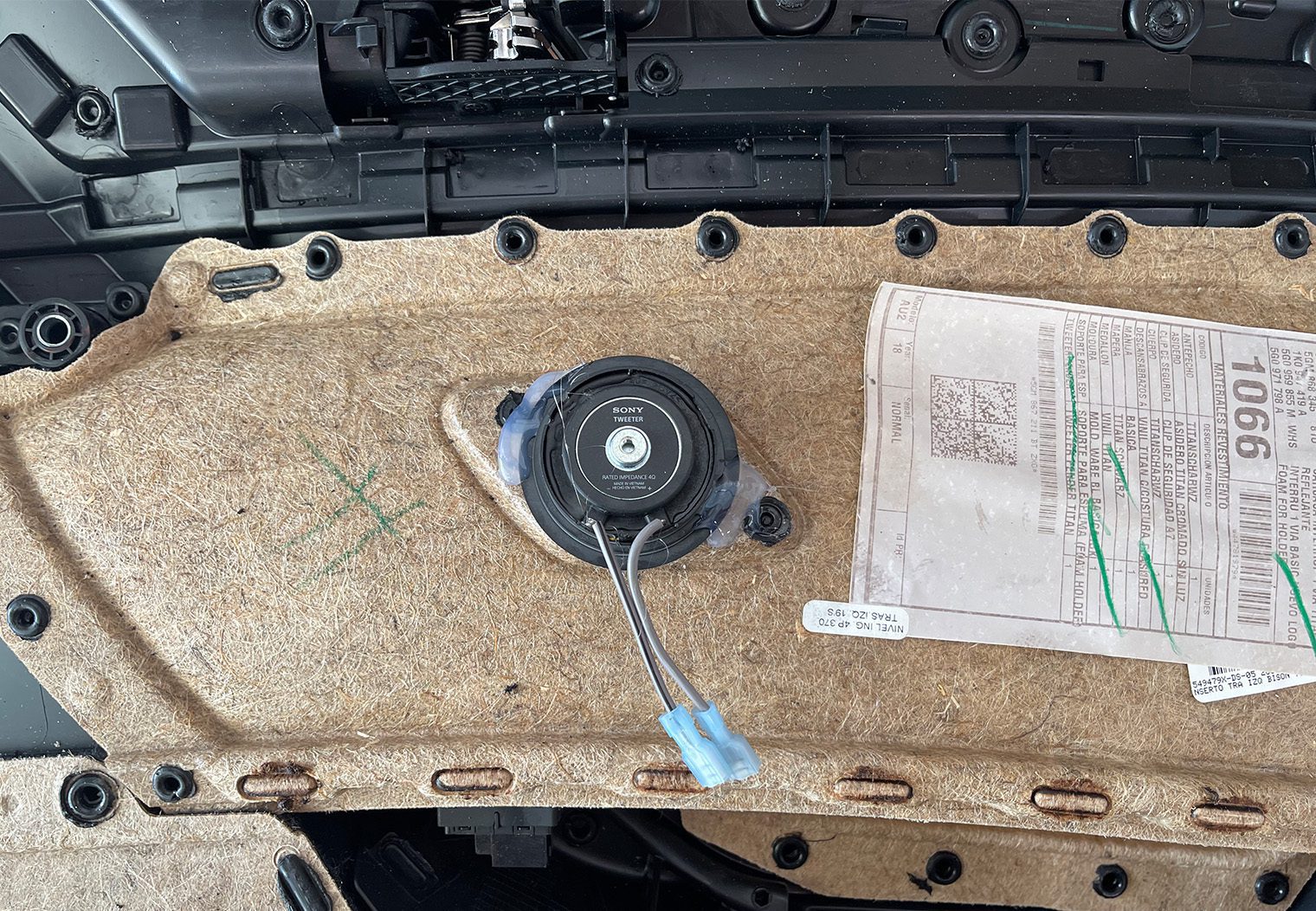
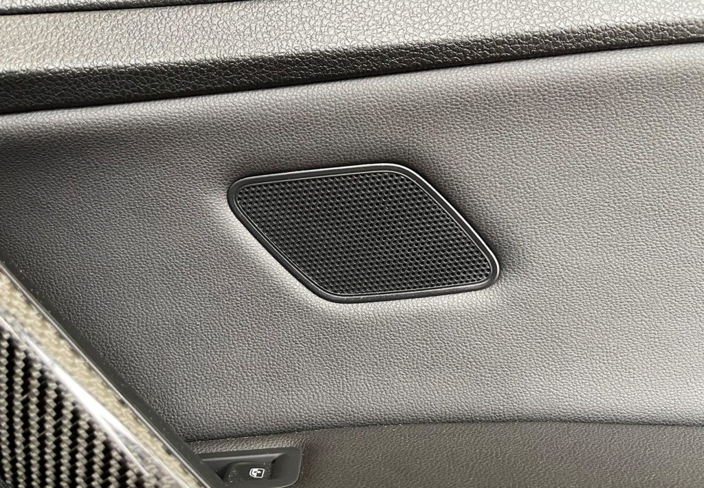
Once your A Pillar trim is removed though, it's pretty easy. The rear door panels house the tweeter too, so these panels were already removed and we had easy access to them. We used a Dremel to cut the OEM Fender tweeter mounts off as flush as possible to the panels and then used a hot glue gun to mount the new tweeters into position. We did this on both the A Pillar trim and the rear door panels. Since these Sony tweeters are built into the housing and the grille, we decided to mount the entire tweeter to the panel, ensuring that the tweeter would not come into contact with the trim piece.
We also soldered some pig tails with quick connectors, and crimped quick connectors to the car's harness as well so that we could easily plug them in while we re-installed the trim pieces and door panels. Here's a few shots of the tweeter installation on the A Pillars and rear door panels.
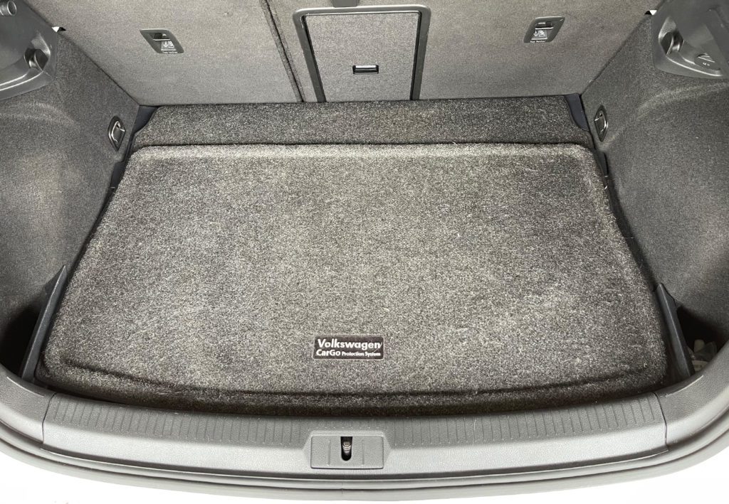
Subwoofer Enclosure & Amp Rack
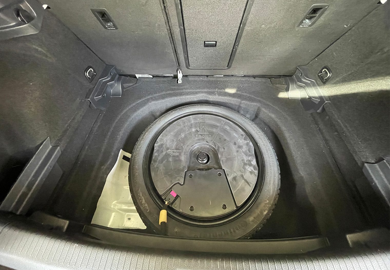
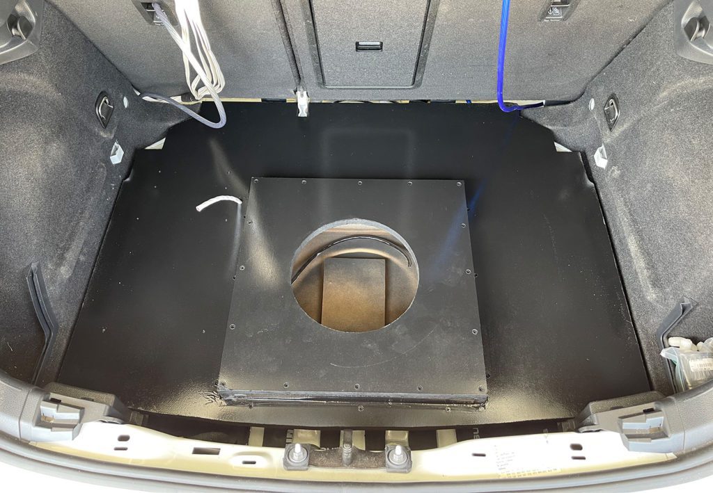
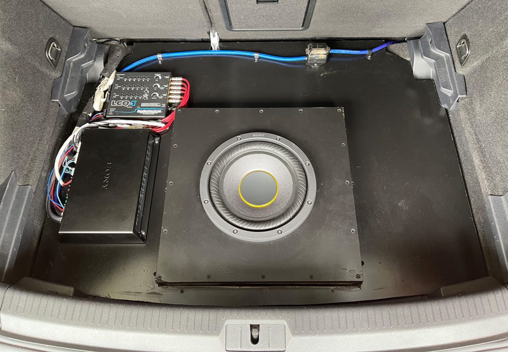
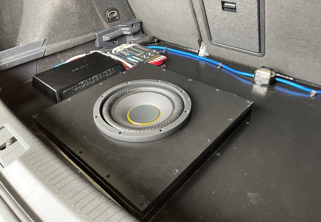
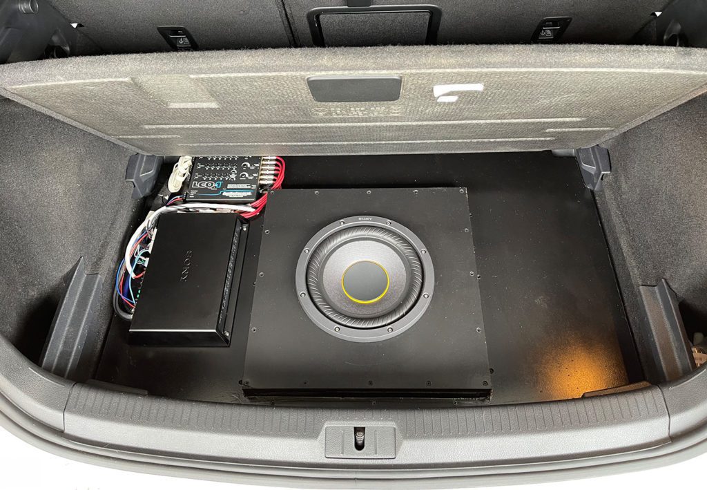
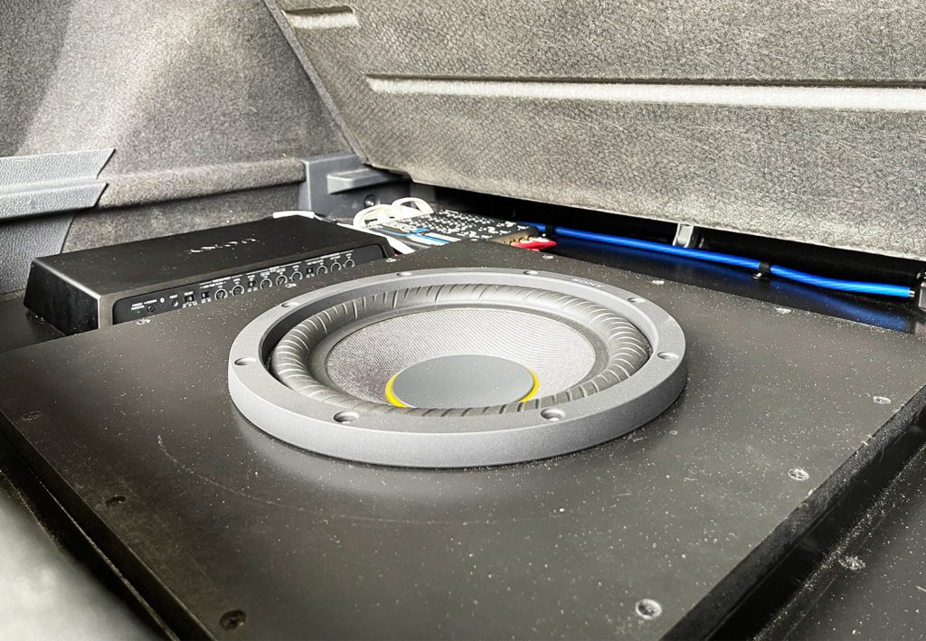
Since we wanted the trunk to be fully functional, we built an enclosure that would sit deep in the OEM spare tire well, surrounded by an artificial floor that we could mount the amp, wiring and the LCQ-1 to. All sits below the OEM trunk floor.

For the subwoofer enclosure, I went with a very simple square sealed design. I build it to match the ~1sqft volume that Sony recommended as best as possible. However given the shallowness between the bottom of the spare tire well and the top of the trunk floor, it ended up being a little under the recommended volume by about 8%. The enclosure was built completely independent of the artificial floor/amp rack.
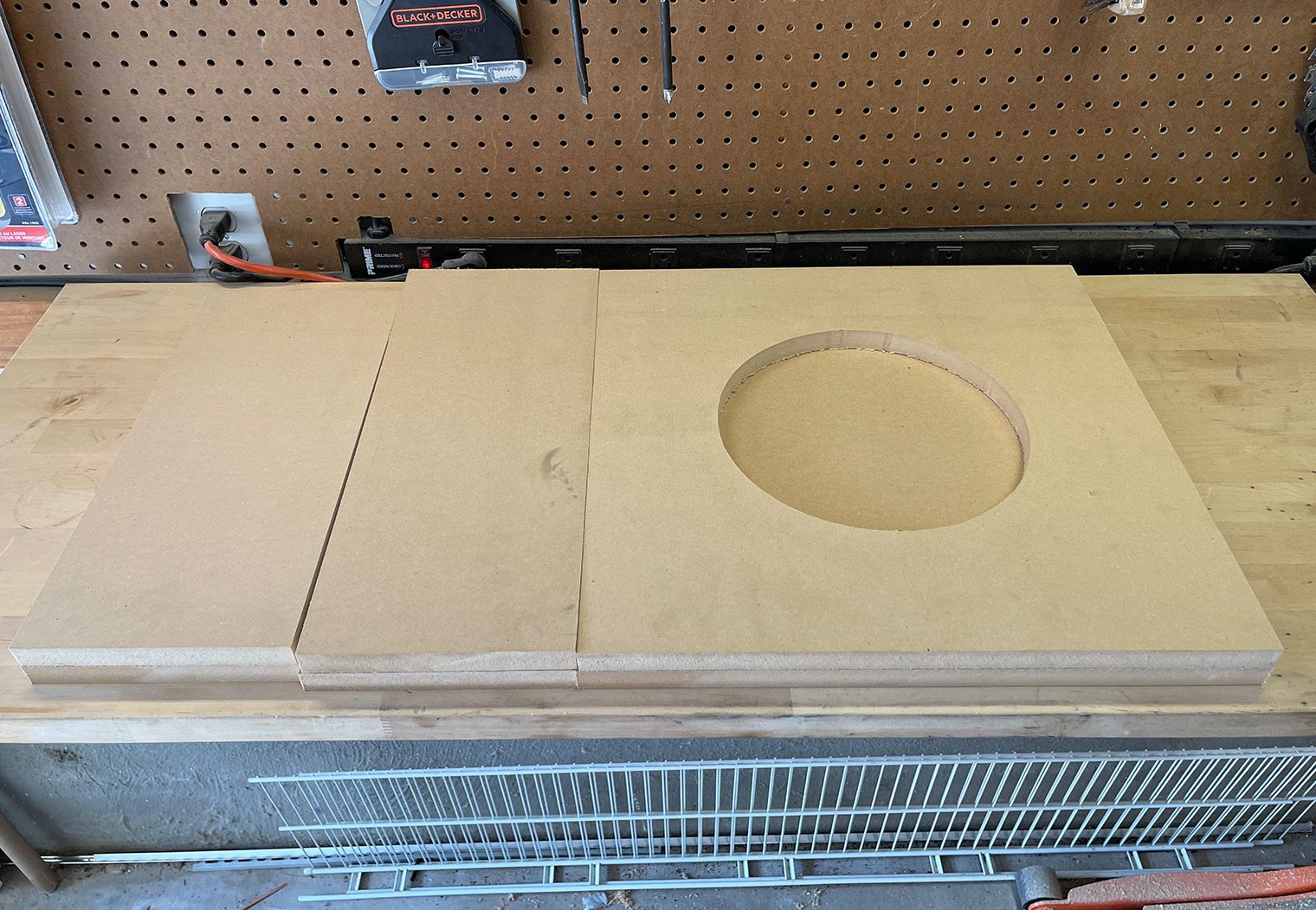
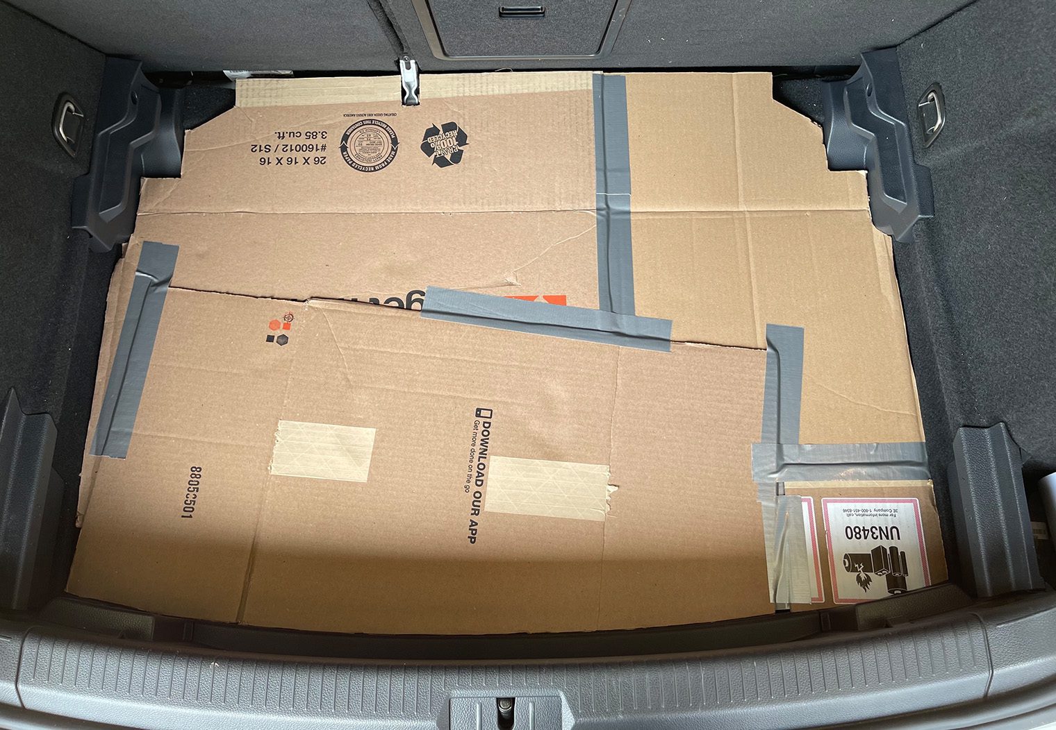
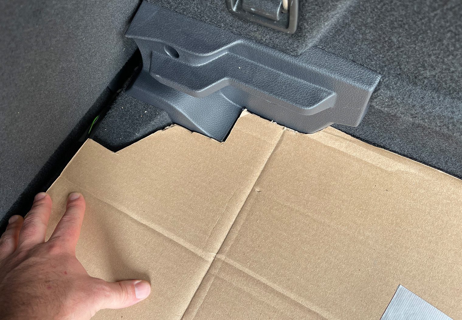
Once I had the subwoofer enclosure built, I made a cardboard template of the trunk space where I was going to create the artificial floor. Then, I cut it out using the leftover MDF that I had from the enclosure. I used a single 3/4″ MDF 4′ x 8′ sheet for both the subwoofer enclosure and the floor.
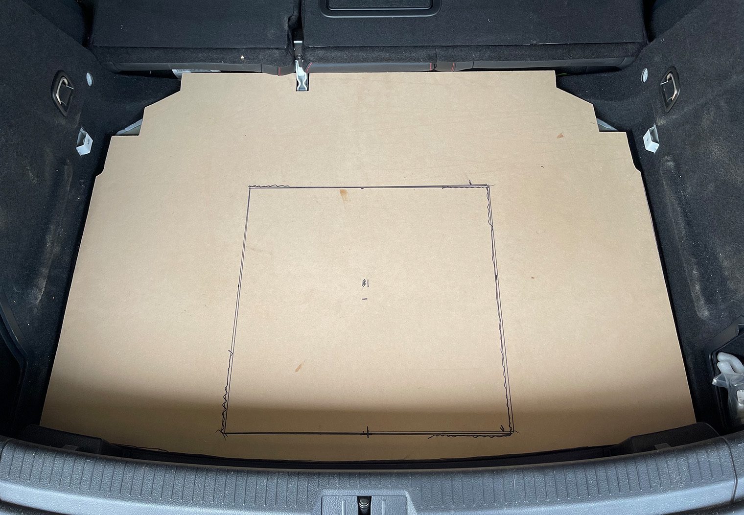
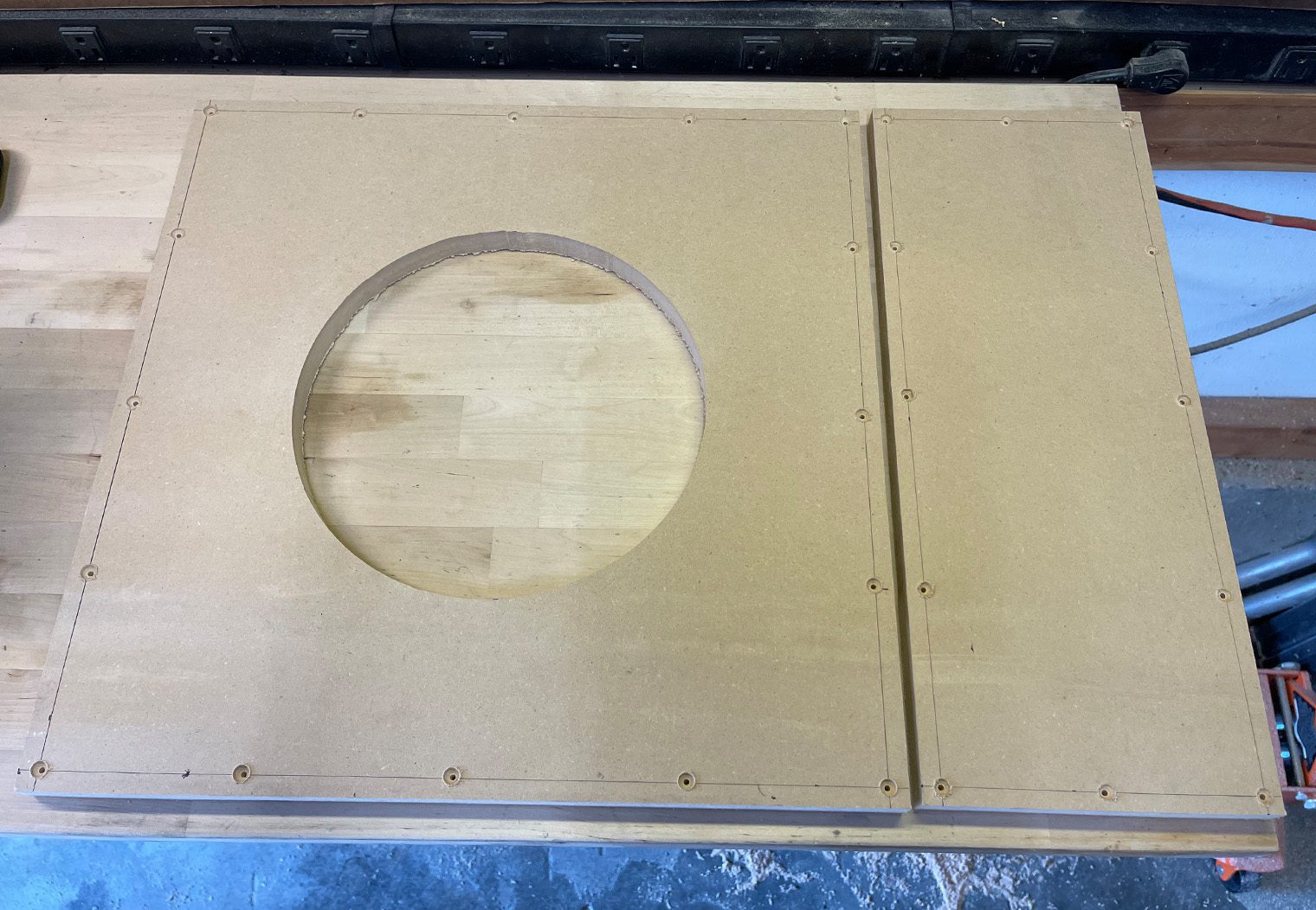
With the artificial floor/amp rack cut I centered, traced and cut out the center of the artificial floor and then I mounted the enclosure to it.
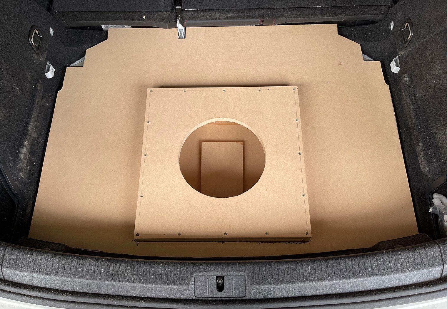
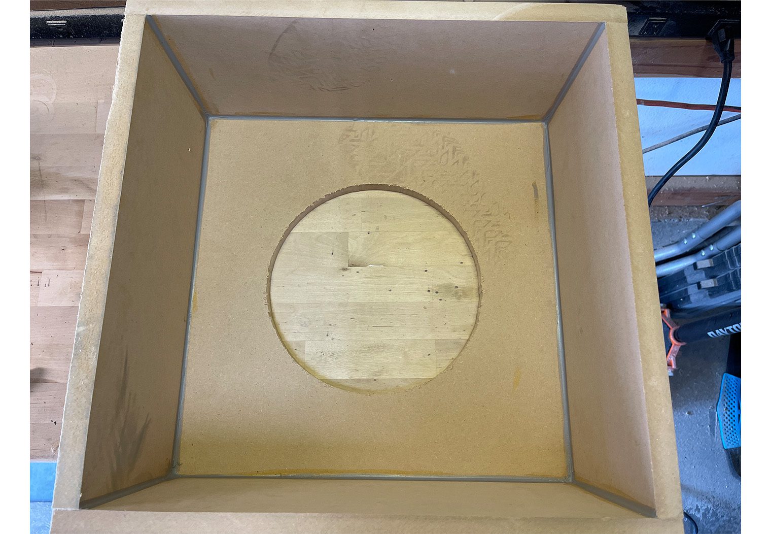
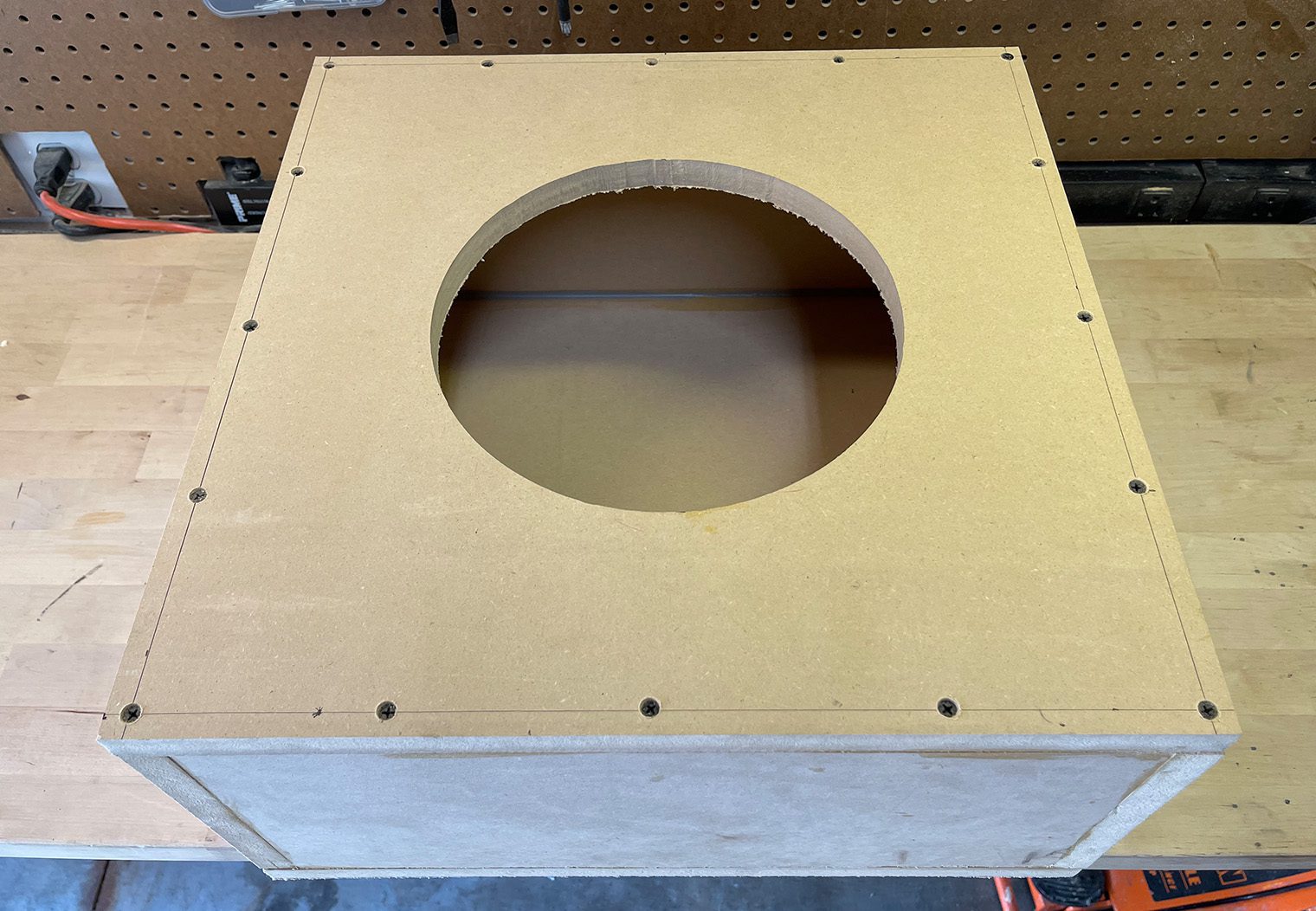
All-in-all, the false floor and enclosure fit very well. The one thing that I will note is the cutout that you see in the center sub enclosure that wasn't in earlier pictures. In order to make the box sit as far down into the spare tire well as possible, we cut a piece out of the center of the box and then sealed it from within with another piece of MDF. This would allow the enclosure to sit around the center ‘bump' in the tire well and sit about 3/4″ further down. This was to give the subwoofer more space between the OEM trunk floor and the top of the woofer.
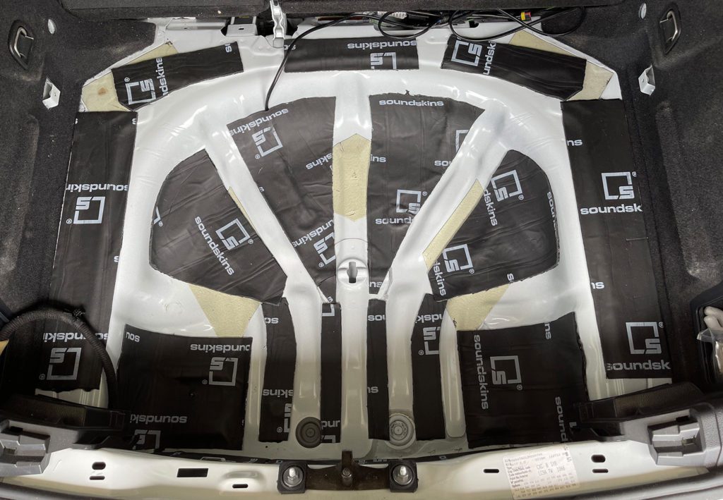
With the enclosure fitted and tested, we moved onto dampening. We chose the SoundSkins Pro Door Kit SSPRO-1 to do this. We actually hadn't used this dampening material before but Mark from CarAudioFabrication recommends it highly so we trusted it was a good choice. There's a ton of dampening choices depending on what you're trying to do, where you're trying to dampen, etc. But this ended up being a good choice for us and what we were doing. you can read more about dampening in our informative sound dampening article.
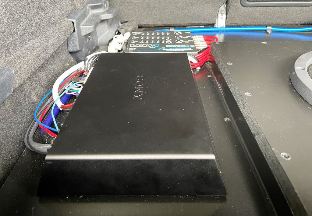
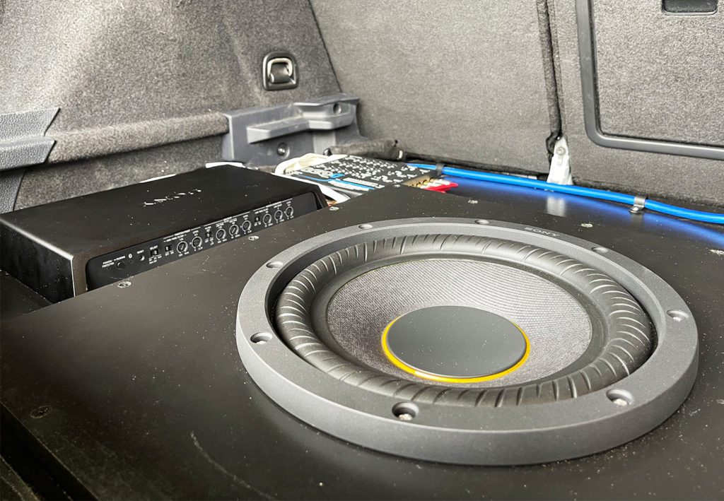
Sony Amplifier & LCQ-1
This is worth a section of its own because of the complexity. In a previous era, a high performance stereo would warrant an upgraded head unit like one we'd recommend in our best car stereos list. You'd install the new head unit and run clean 5v signal to the aftermarket amplifier. Done.
Today, however, many of the features of the vehicle (and the control of those features) are baked into the head unit. Things like gauges, vehicle customization options, so on – the head units are deeply integrated into the electrical systems and features of the car. It certainly was with this MK7.5 at least. And although this is an awesome capability from the factory, it's not ideal for the audio enthusiast who want to upgrade. Finding a clean, quality and unaltered audio signal is becoming more and more challenging these days. This makes an aftermarket, high performance stereo more challenging to install.
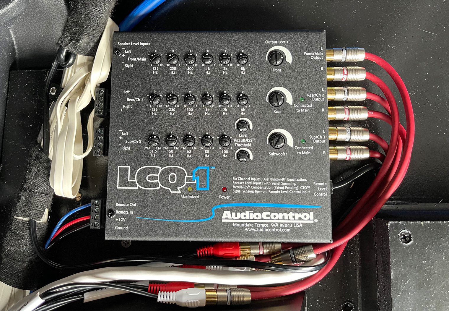
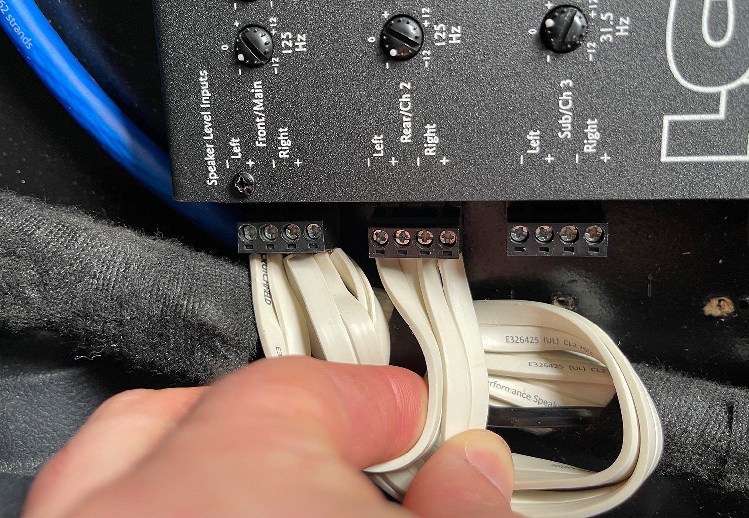
This is why products like Sony's XM-GS6DSP amplifier w/DSP and AudioControl's LCQ-1 line-input converter with EQ exist. Sony's XM-GS6DSP can take high inputs as it's signal directly from the output of your OEM head unit and/or amplifier, process it and then provide you with amplified outputs for your system. The LCQ-1, on the other hand, will take high outputs from your OEM head unit or amplifier, process the signal via an EQ and convert them into low voltage signal for your amplifier via RCA outputs.
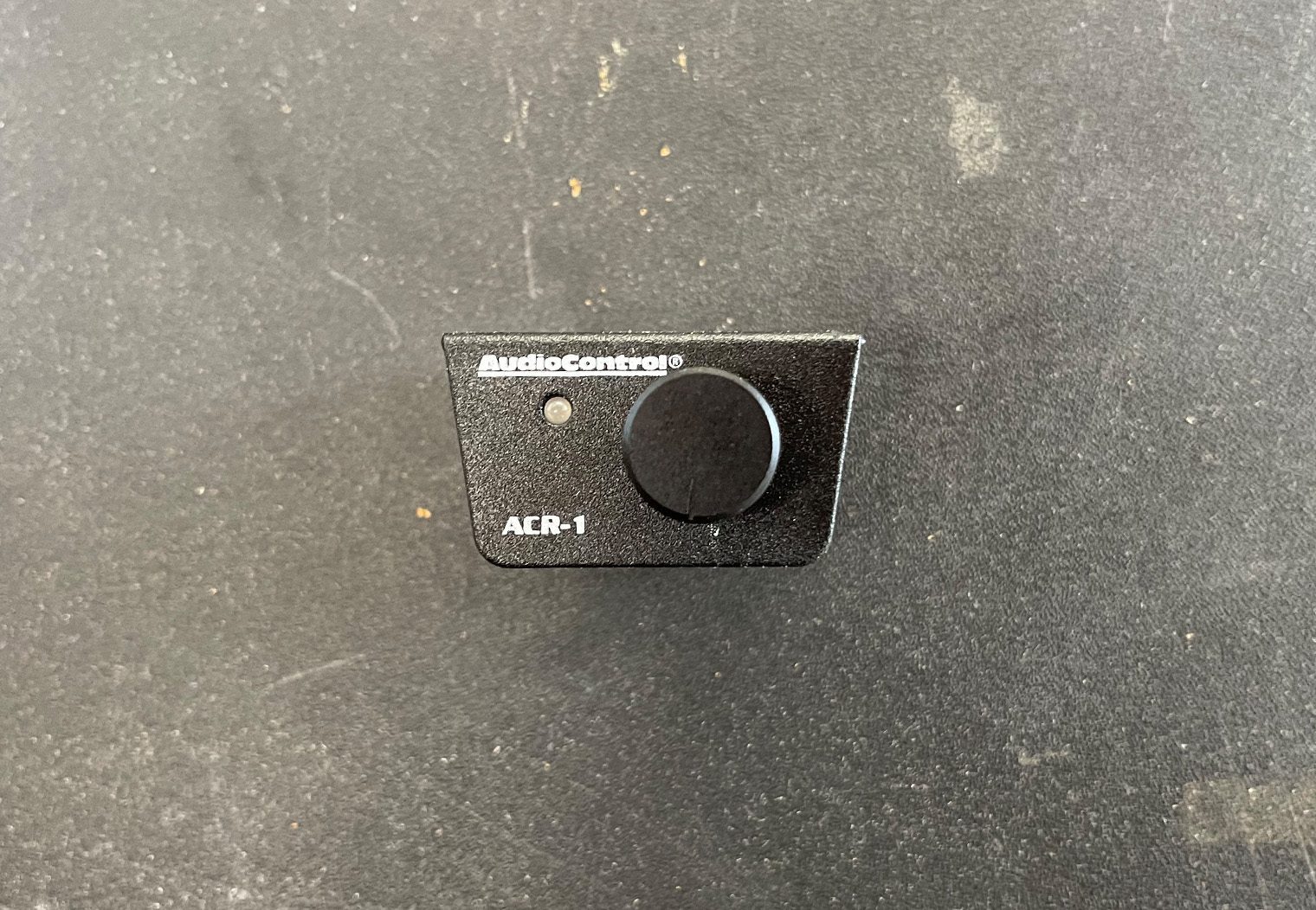
You might be wondering why we chose two products with relatively redundant features (EQ/DSP). It's kind of simple – we wanted control of our subwoofer via a manual control knob AND DSP/EQ control. Sony's XM-GS6DSP could have taken the signal that we used (see the section below) and given us control of the sound via their DSP and subwoofer control via their subwoofer level controls. All baked into a nice app on your phone. The problem we had with that is that subwoofer control on a high performance system like this is really dynamic, and pulling your phone out to alter the levels while you're driving is less than ideal. In order to have separate subwoofer control AND EQ, we needed the LCQ-1. This ultimately rendered the DSP functionality in the Sony Amplifier useless in this configuration.
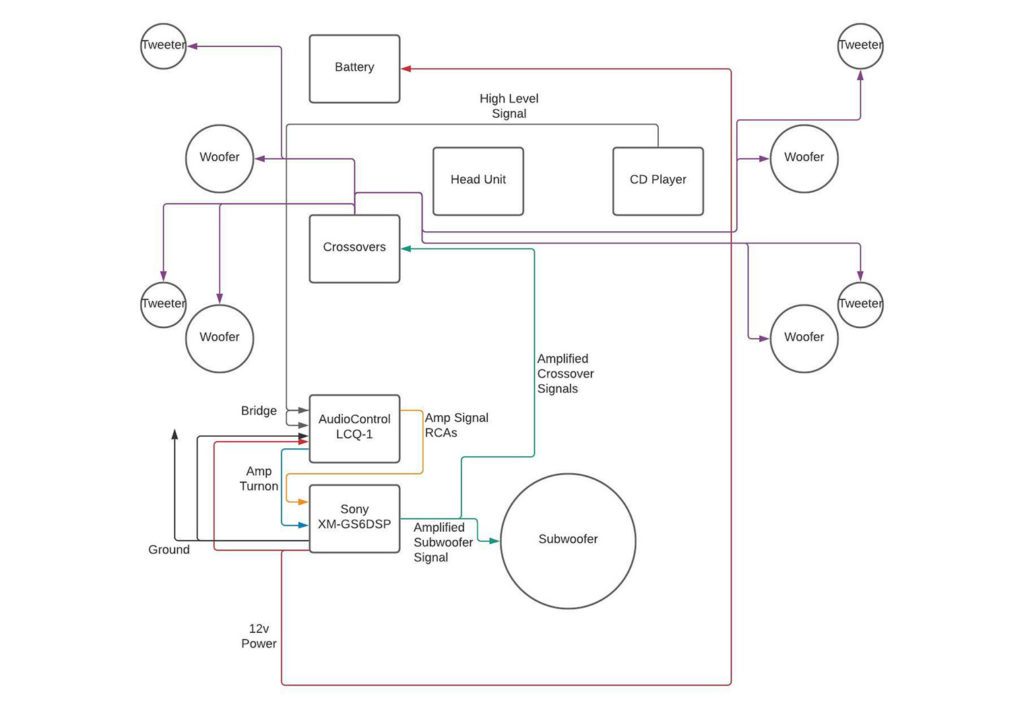
In our setup, the LCQ-1 takes the OEM signal, processes it based on the EQ settings we chose during tuning, and converts it into Front, Rear and Subwoofer outputs. These outputs are used in the ‘6ch' configuration of the XM-GS6DSP (which doesn't offer DSP control) to power a 5 channel system – Two fronts, two rears and a subwoofer. Vomit.
Signal & Wiring
Now that I've given more context about the head unit and signal, this section might make a little more sense. But yikes. This was a tough part of the installation. Some of this was trial by error but I really have to give a shout out to some of the guys in the forums for the programming instructions, pin configurations, etc because without them this would have taken twice as long at least. I've added a bunch of the forum pages to the source section of this article if you want to check them out and see where I grabbed some of the information that really helped with this install. If not for the Fender system and amplifier this likely would have taken us half the amount of time. Wiring and programming took about 5-6 hours in total.
Signal
Let's start out with finding a signal for our aftermarket Sony amplifier. From the factory, this GTI MK7.5 with the Fender system is equipped with an amplifier that's located underneath the driver seat. Signal is sent from the back of the CD player in the glovebox to the amplifier via fiber optic cables so you can't tap into the signal there. You could tap into signal via a line-input converter like the LCQ-1 from the OEM amplifier's outputs. But at the time it seemed like an inefficient way to get a signal – a non-amplified signal that's amplified, only to be converted to a 5v input signal and then amplified again to the speakers…
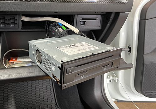
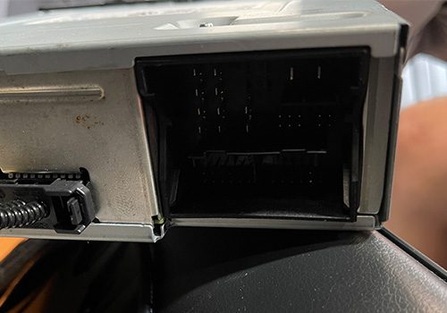
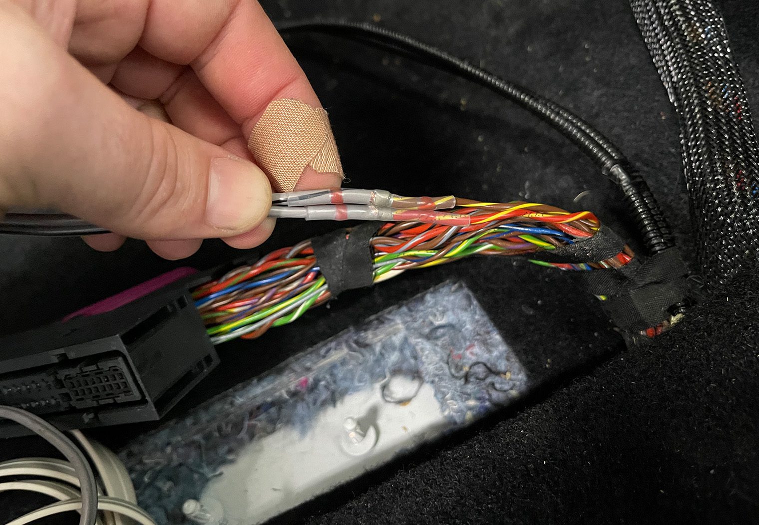
So I have to again give a shoutout to some of the guys on the forums, in particular q2quest here where he outlines the pin configuration and more importantly the fact that you can use and OBDEleven to program the Fender head unit to output a signal that we could use with our LCQ-1. To simplify the process, we tapped into pins 6/2 and 7/3 in the diagram below for the signal, and wired them to the main line input on the LCQ-1 (bridging the main and 2nd channel inputs). Here's a diagram to help you pinpoint the pins to tap into on the back of the CD player in the glovebox.
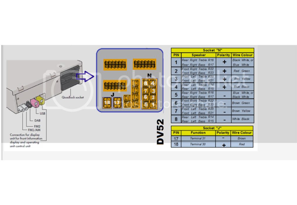
I purchased an OEM 8-pin connector that would fit into the location “N” along with four N 906 844 05 female terminal connectors to crimp and input into the 8-pin connector. From the factory, the Fender systems don't have this plug since it uses fiber optic cables to run signal to an amplifier. The output wires from this 8-pin connector will ultimately get wired to the line-input connector and used as the amplifier's signal. I'll talk more about it in the wiring section.
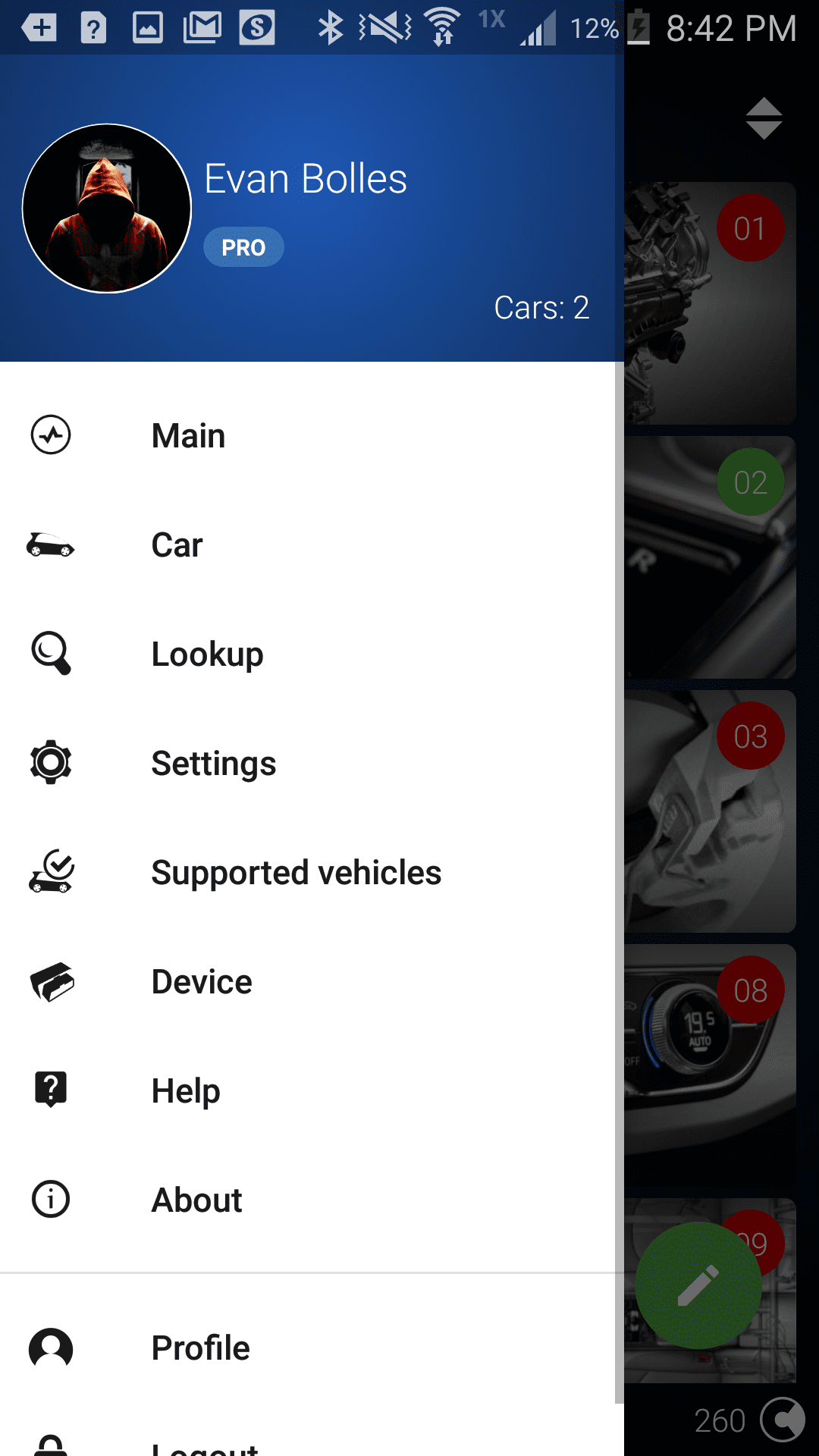
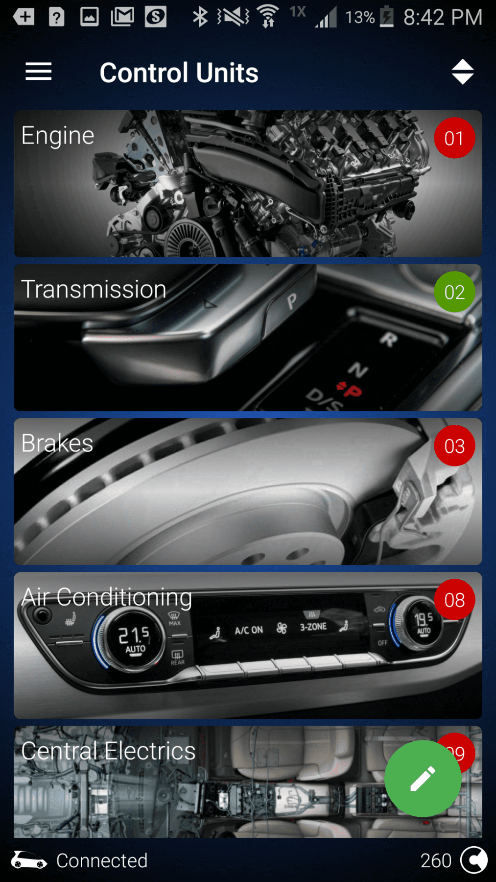
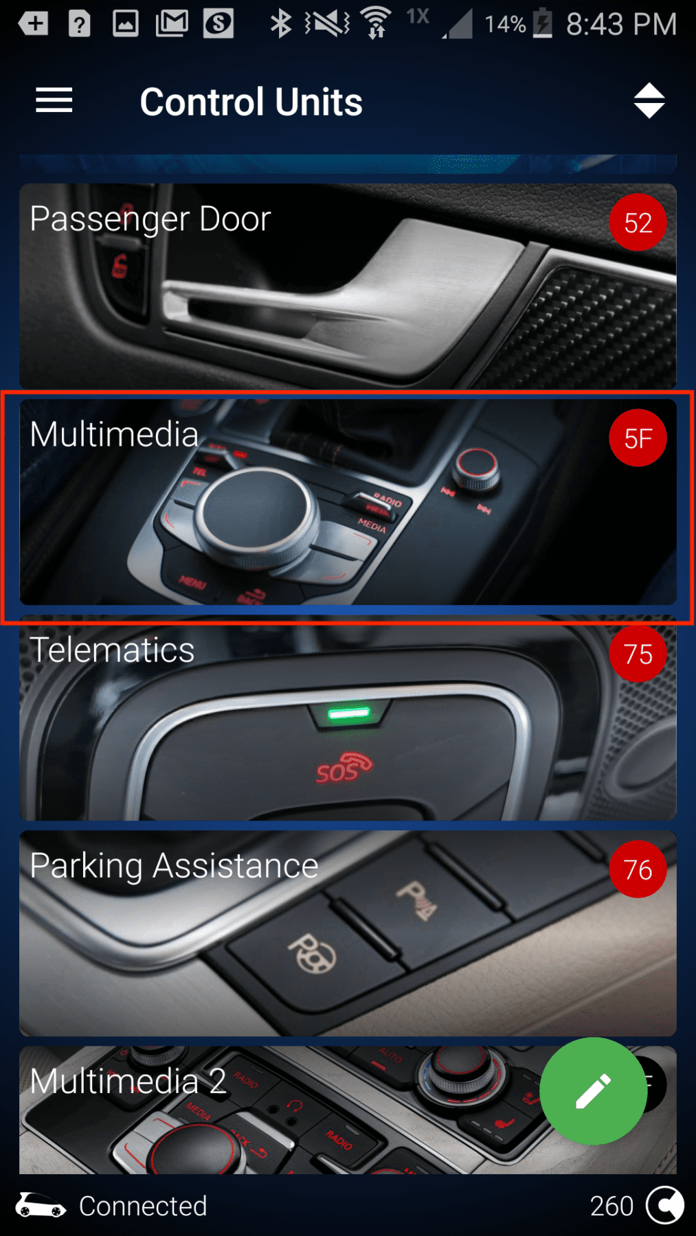
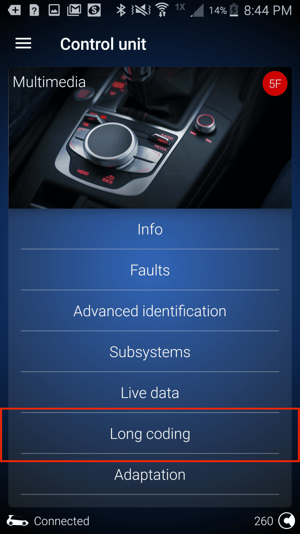
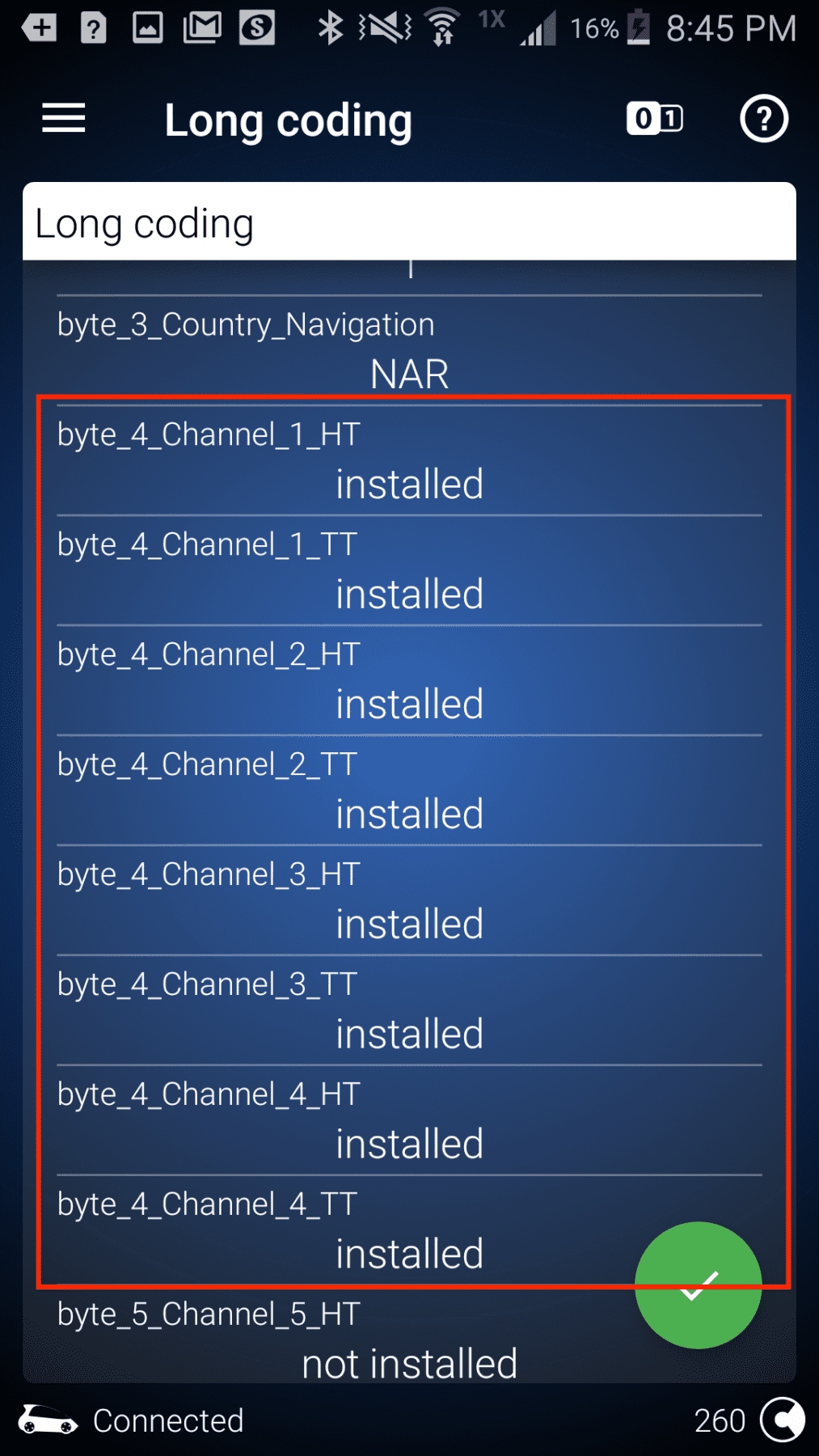
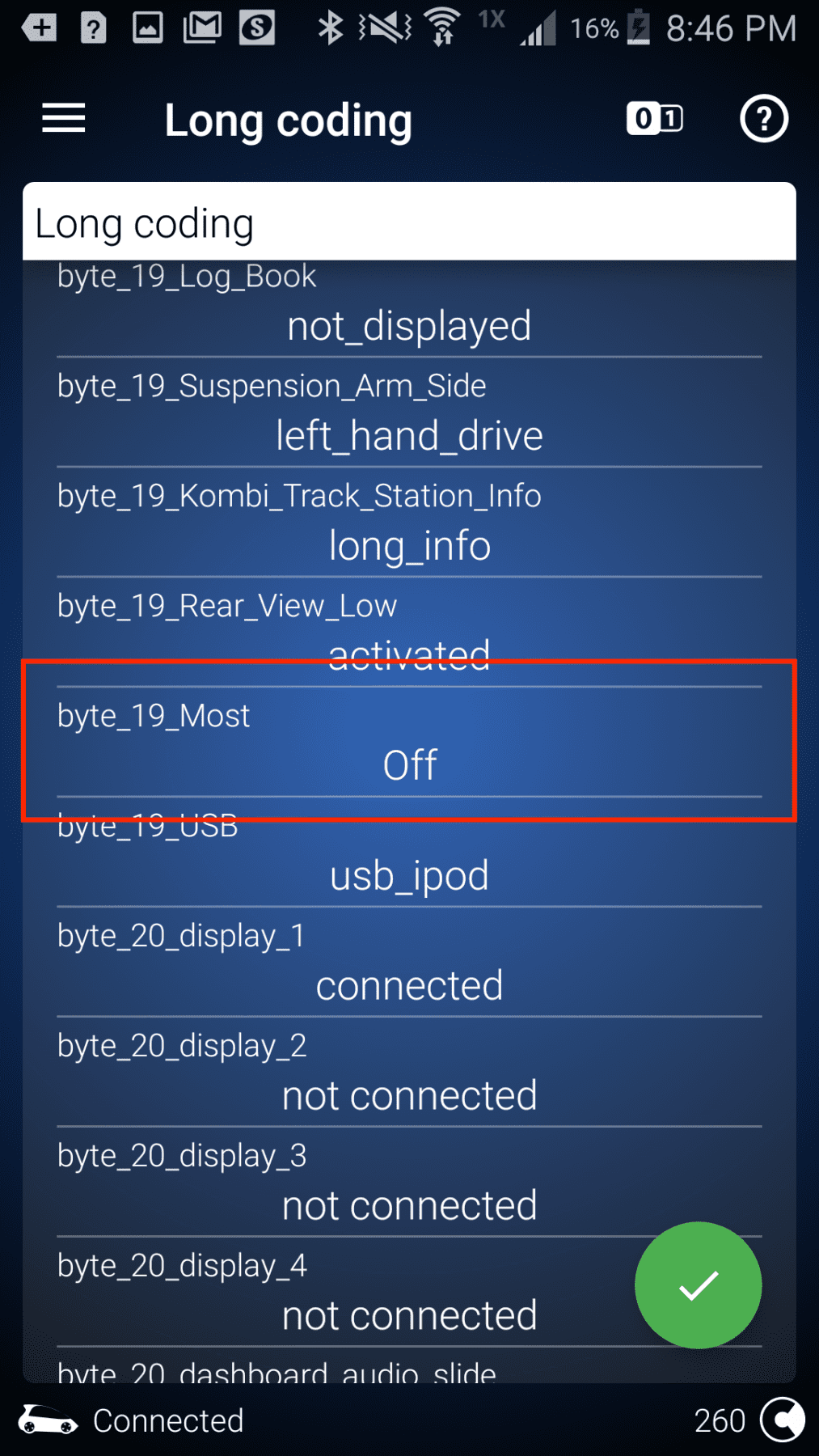
After we wrapped up the signal wire on the back of the CD player, the next step was programming with the OBDEleven. In order to do this programming, you'll need the upgraded “Pro” plan. Not the “Ultimate”. This will give you access to additional modules and “Long Coding” functionality in the app that are required to program the head unit to output a signal on the four pins that I identified above. Here's what the programming process looked like for me.
Wiring
Programming and signal aside, the wiring wasn't all too challenging but it was still time consuming. Continuing where we left off with the signal wire after programming the Multimedia system with our OBDEleven, we ran the signal wire from the back of the CD player along the driver side and back to the amplifier in the trunk. To get it to the driver side, we pulled the OEM head unit and trim and ran the wire behind the dash. We did it this way because we ran the power on the passenger side away from the other speaker signal wires that would lead to the crossovers.
In total, we ran six sets of speaker wire along the driver side back to the amplifier area in the trunk. It ended up being about 60-70ft of speaker wire in total. Here's what we ran:
- Amplifier signal: This is what came from the back of the CD player and was used as the ‘main input' on the LCQ-1.
- Front output (power): Amplified power from the Sony amplifier for the speakers in the front.
- Rear output (power): Amplified power from the Sony amplifier for the speakers in the rear doors.
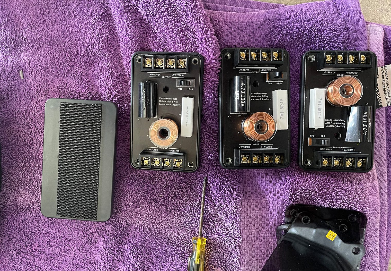
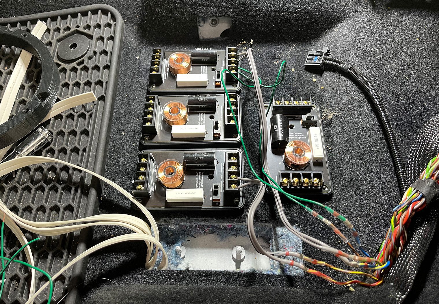
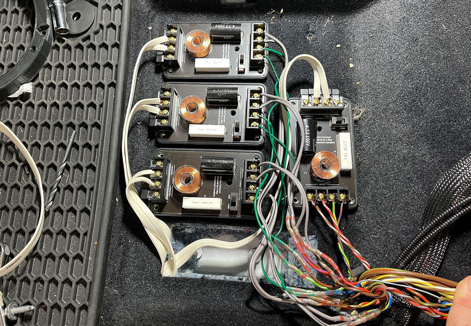
We chose to use the OEM Fender amplifier's location for all four of the crossovers underneath the driver's seat. Here, we ran the outputs (1 and 2 from above) to the crossover inputs, and then tapped into the factory harness for the crossover outputs (using the speaker wire color chart above) so that we could power the speakers without having to re-run all of the speaker wire throughout the car. This worked out nicely.
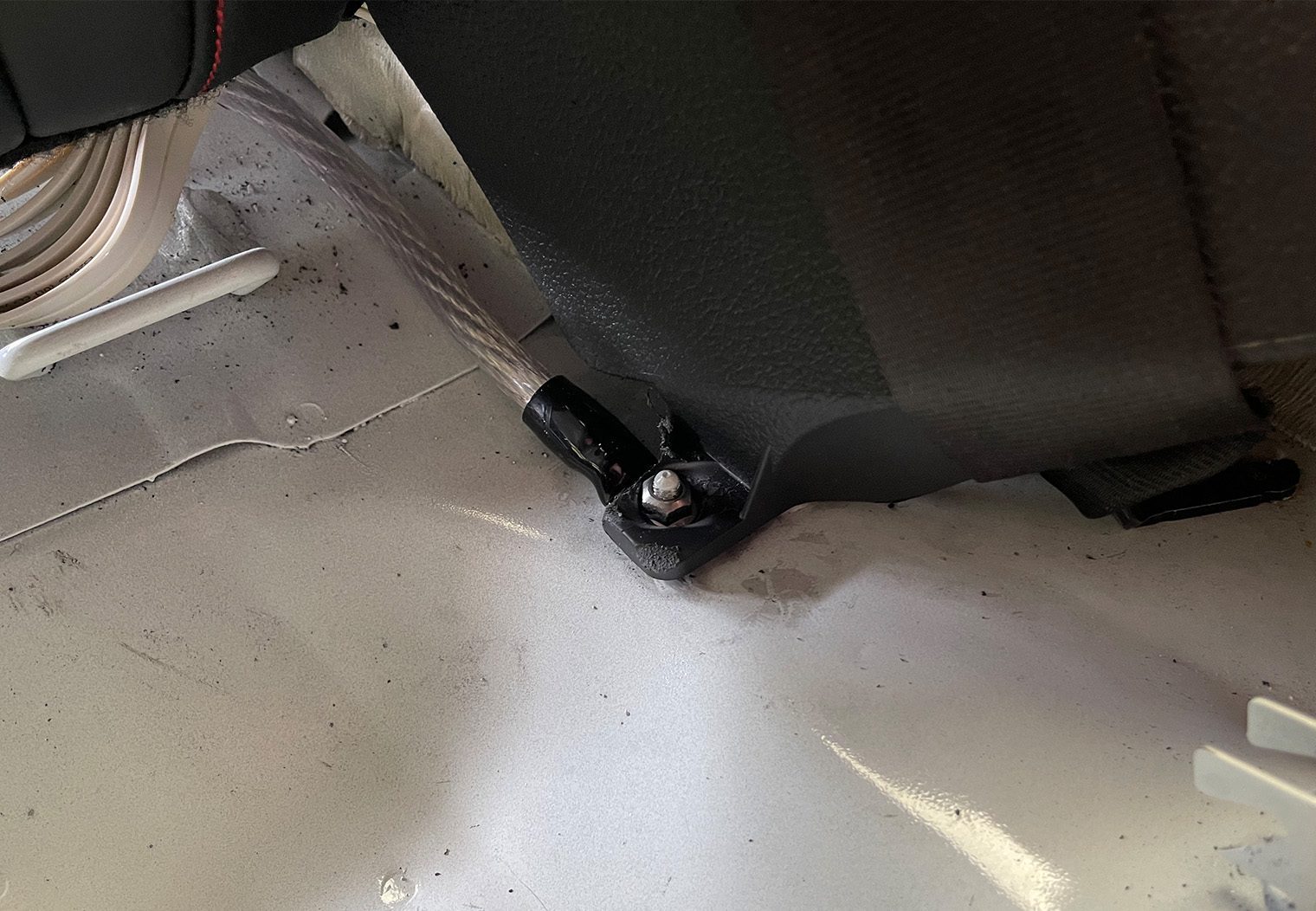
For the amplifier's power, we ran the positive from the battery along the passenger side of the car, away from the signal wires. This also gave us enough room in the trim panels along the side of the car since all of our signal wires were tucked along the driver side. And for the amp's ground, we leveraged one of the mounting bolts to the rear passenger panel (used a Dremel first to expose the metal beneath). This was only a few feet from the amp location and was easy to access.
And with power and ground wired to the trunk area, we tapped into it to power the LCQ-1 as well. And for the amplifier's remote turn-on, we chose to use the LCQ-1's ‘GSO' feature that would send a 12V signal to the amplifier whenever it detected that the head unit was on. It's worth noting that in order for us to get signal output for front, rear and subwoofer channels from the LCQ-1, we had to bridge the main input and channel 2 input on the unit. This would allow the LCQ-1 to send signal from front, rear and subwoofer to the Sony amplifier via 3 separate RCA channels and give us the control we wanted of the subwoofer.
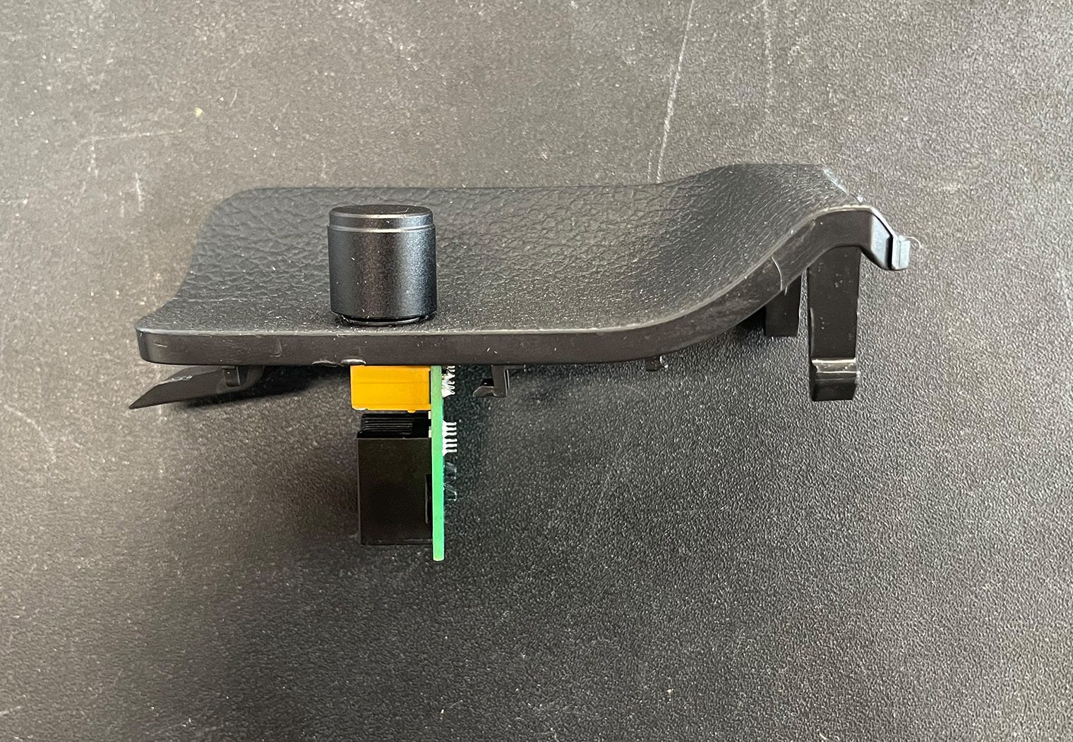
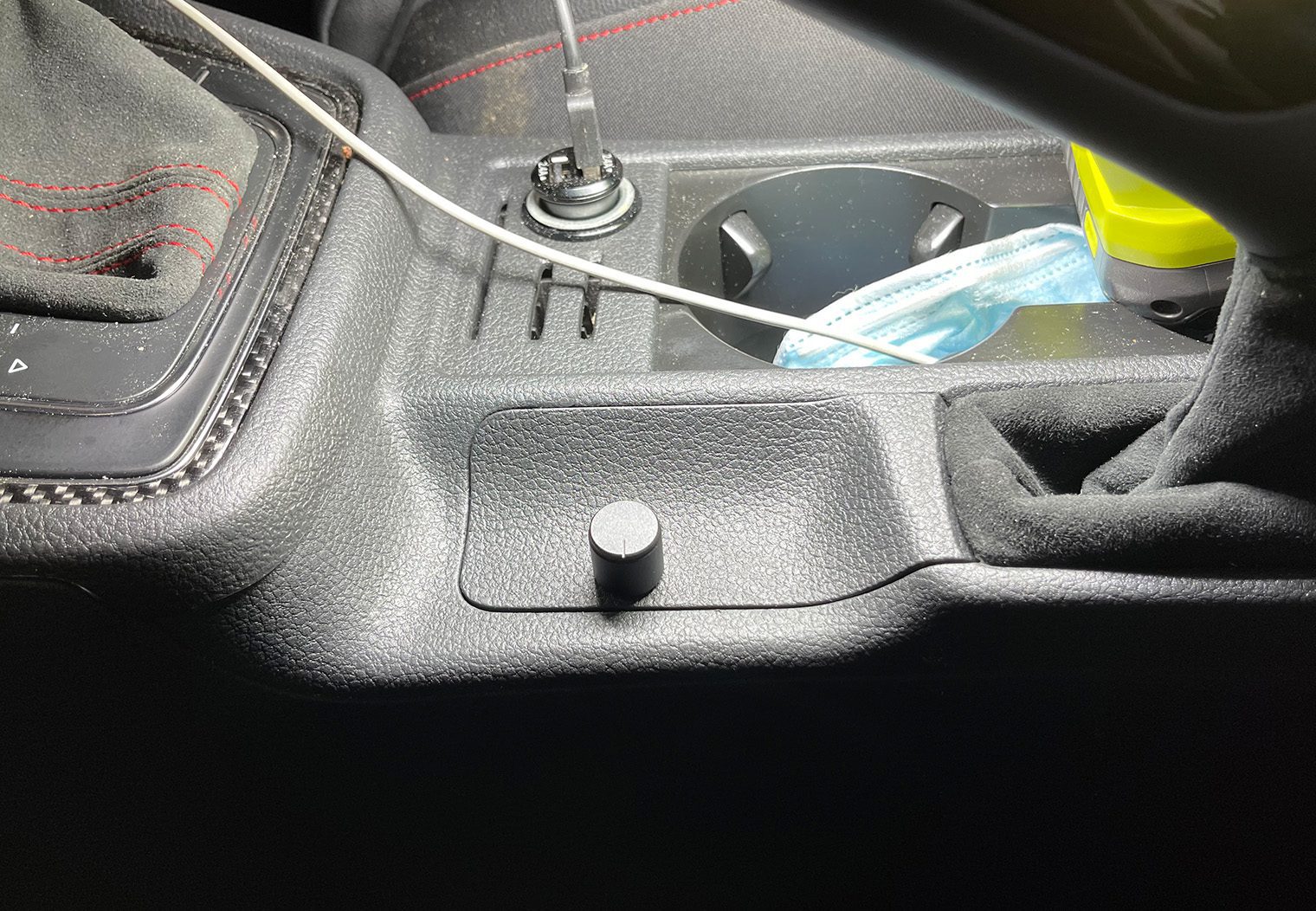
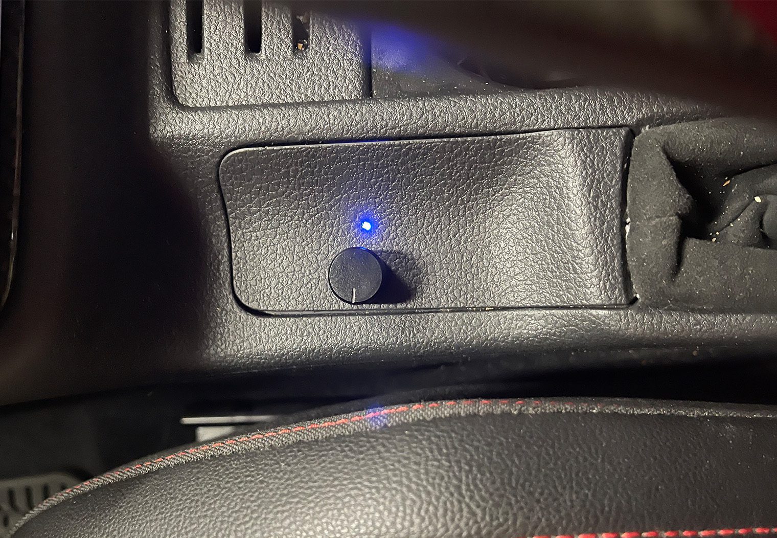
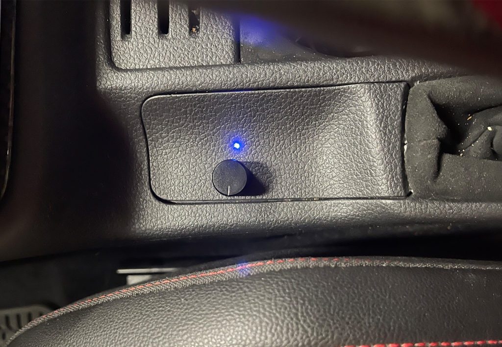
Finally, for the subwoofer we bridged the 5/6th channels on the Sony amplifier and ran the wire directly to the terminal that we installed on the sub enclosure. And from the LCQ-1, we ran the subwoofer control wire to the center console just in front of the emergency brake.
Here's a look at the wiring that was required for this install.
End Result & Opinion
I said this up front in the intro of this writeup but I'll say it again – upgrading an already upgraded stereo like the MK7.5's Fender system is a commitment. The way we chose to do it here is not the most efficient way by any means. But the result was very rewarding. Volume, clarity, fullness – the stereo's performance was on another level after this installation.
The detailed output from Sony's Mobile ES speakers, when combined with an amplifier like their XM-GS6DSP, is pretty incredible. Especially for the price. A decade or two ago, you'd need twice the space for amplifiers, more speakers and more power to get the volume and clarity that this stereo produces. And the control that the LCQ-1 gives you over the OEM input signal really makes an aftermarket stereo doable in any modern car with a high-quality signal for your amplifier.
All-in-all we enjoyed this install and are thrilled with the outcome. But I wouldn't necessarily recommend this setup on an MK7.5 w/Fender for the average weekend DIYer!
Final Photos


Nice job. I installed the XM-GS6DSP myself recently in my ’17 Ford Fusion hybrid. I think what I might have tried instead of using the LCQ-1 for remote bass level control (while also retaining an EQ) would have been to just keep the amp in 2ch. DSP mode and use an LP7-4 for the speaker outs and LP7-2 for the sub channel. Much less expensive. This way you can run the LP7-2 RCA output to a LC-1 RCA-level knob and output to the sub channel line-level RCA input on the amp. I haven’t tried this myself but, in the manual it says to keep the sub channel LPF in the on position in DSP mode, thus it’s possible that this config would work in 2ch./DSP mode.
were you able to recode everything using the odbelven?
What’s the deal with buying credit for the odbeleven?