In this article: This article is part 2 of a multi-part series install, documenting a custom stereo installation on my 2021 Ford F-150. In this article, I'll walk you through the steps I took to prepare all of the components for installation in my F-150, including the amplifier rack, wiring prep, subwoofer enclosure and more.
In part 1 of my F-150 stereo build, I walked through all of the planning and decisions involved in purchasing all of the products for the build. I outlined things like goals, speakers, amplifiers, subwoofer choices and more. These are the core decisions and components that dictate the preparation in this article so if you haven't browsed through part one already, I would recommend you do before reading this article! You can also find a list of all of the parts that I used throughout this build on my 2021 F-150 Stereo Buildsheet.
Check out all related articles to this F-150 Custom Stereo
Preparing the Power and Ground Wiring
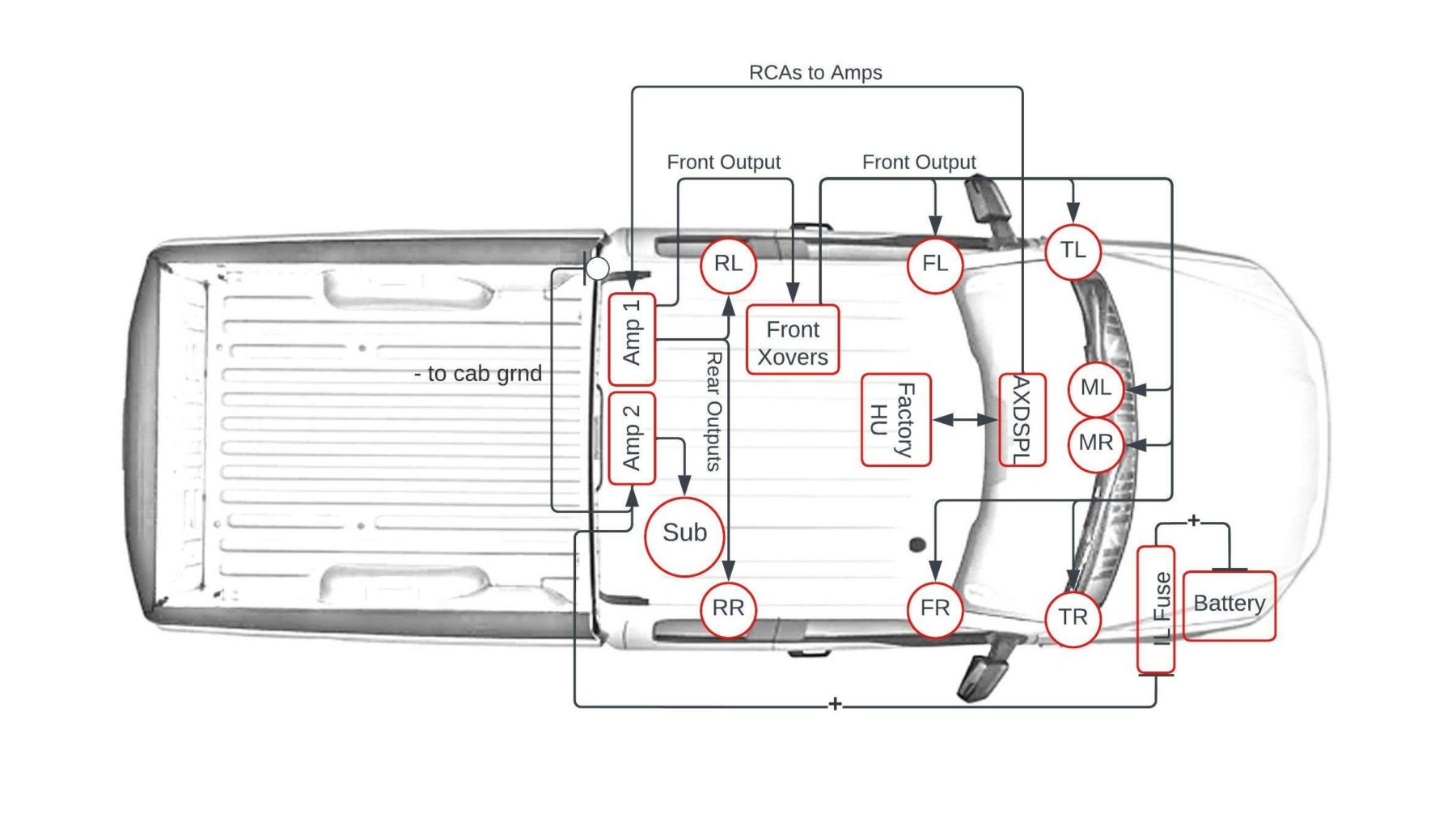
One of the first things I set out to prepare for this build was the wiring. I went through and mapped out exactly where I wanted my components to be installed and rough-measured distances, locations and so on so that I could have all of my wiring labeled and rough-cut before I even began installing everything. Here's what I based my measurements on and how I prepared to install and wire the various components in the truck:
Custom In-Line Fuse Holder Bracket
Find this custom fuse holder 3D printed file for download here.
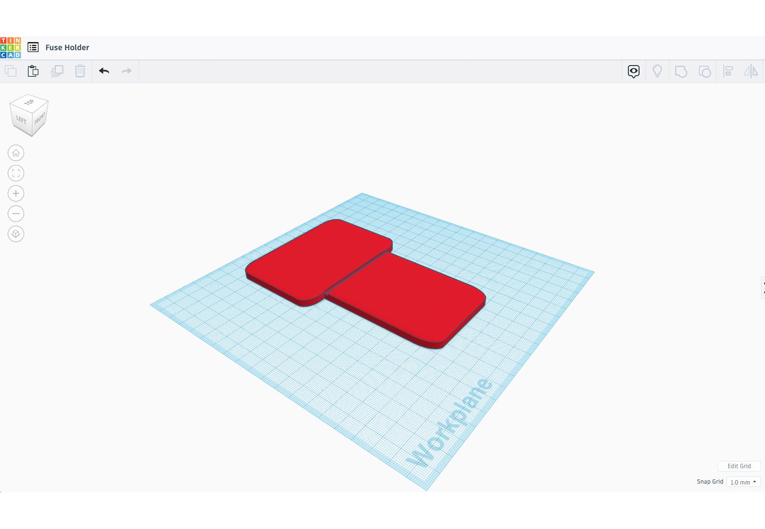
Although there are a few great places to install an in-line fuse within the engine bay of this truck, I wanted a bit more of an integrated look. So I set out to create my own custom fuse holder via my 3D printer.
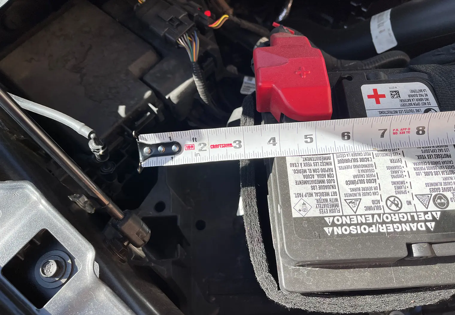
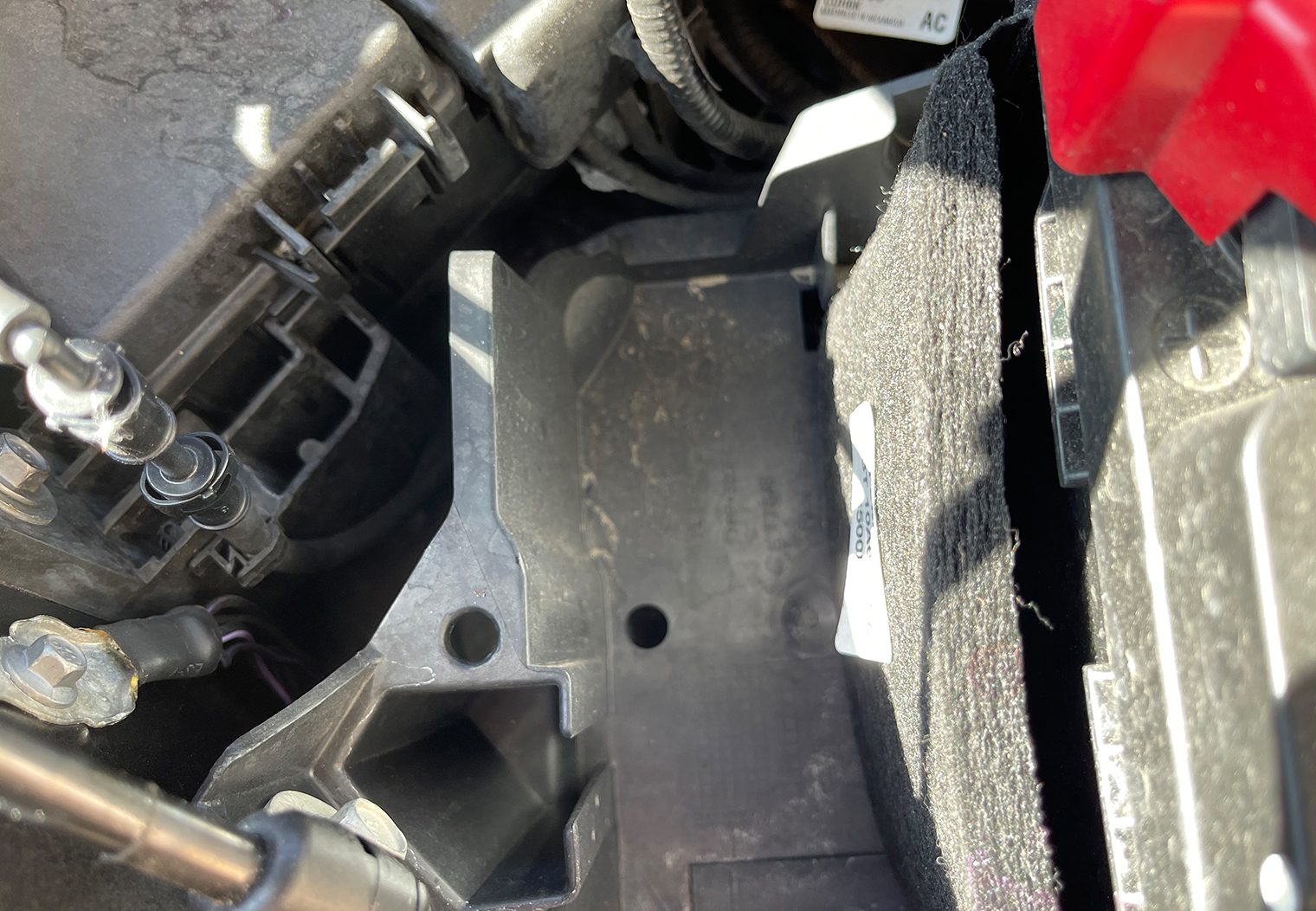
The goal was to secure the in-line fuse holder as close to the battery as possible and away from heat while eliminating any movement in the fuse holder and power wire. This F-150 has a perfect location to fabricate a mount, whether its out of aluminum, steel or plastic. Here's a few snapshots of the area around the battery. My plan was to mount it on the cab side of the engine bay where there's an opening between the battery and the battery box.
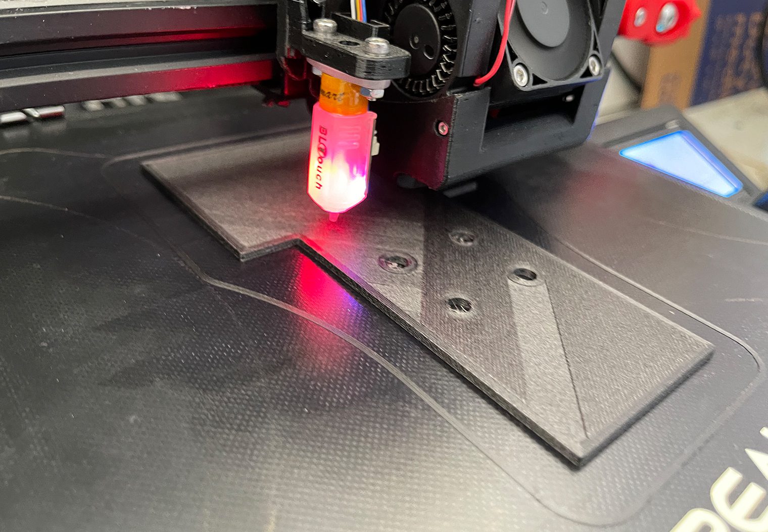
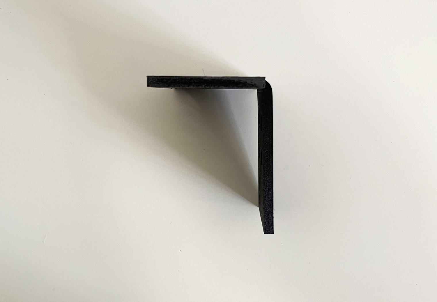
I chose Carbon Fiber Polycarbonate since that's the heaviest duty, highest melting point material I had for my 3D printer, and set out to design my own custom bracket.
After printing it out, I used a heat gun to put a 90 degree angle on it so that the fuse holder would sit on the top, making any potential fuse swaps easy and accessible.
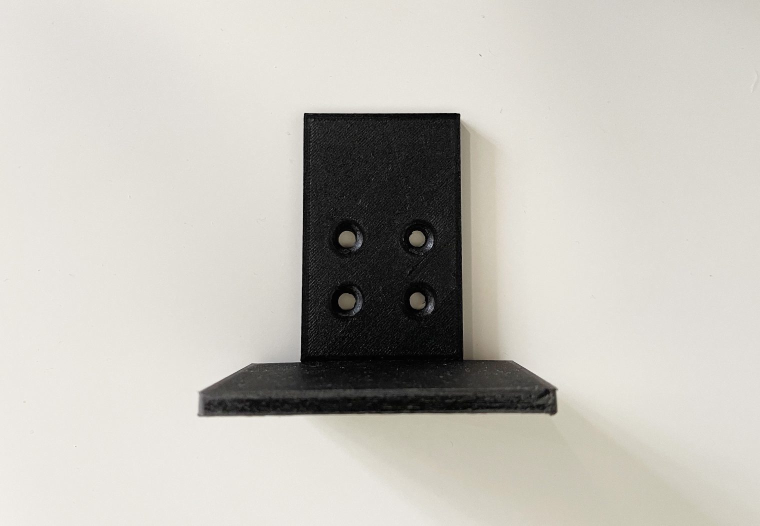
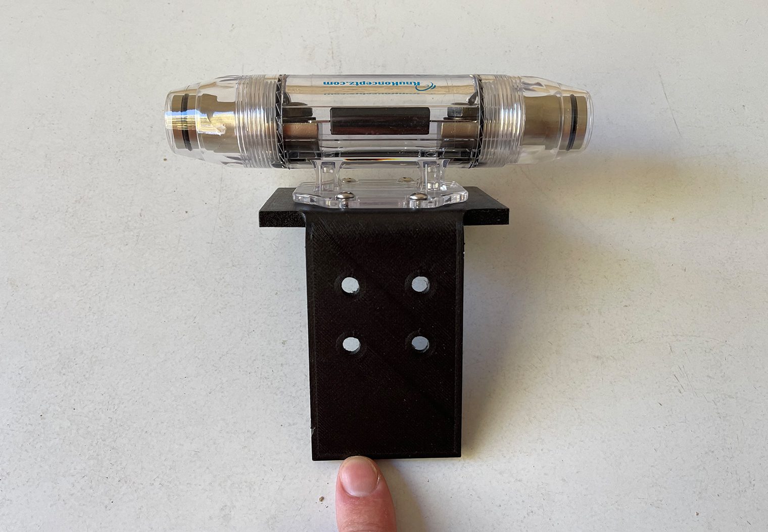
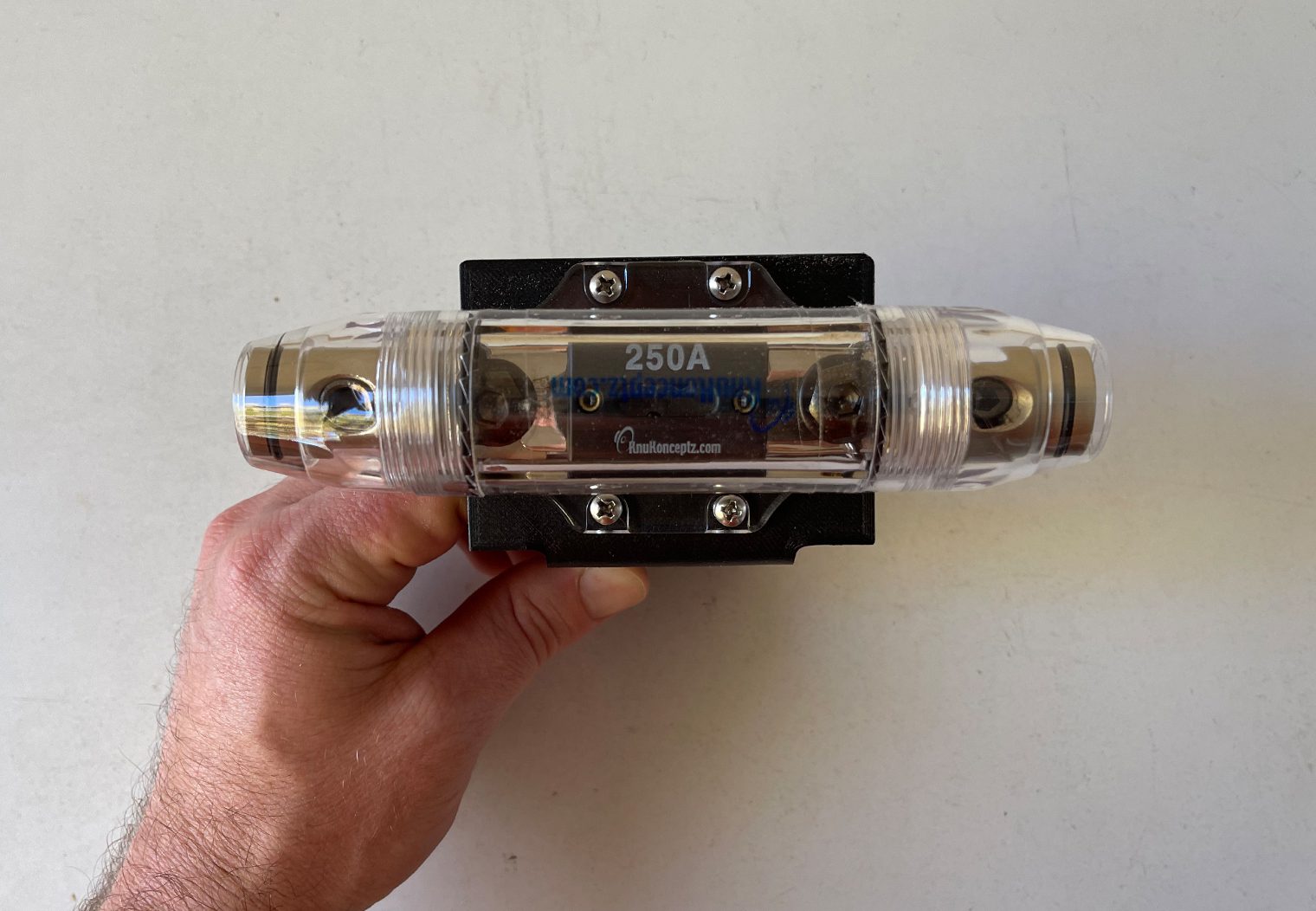
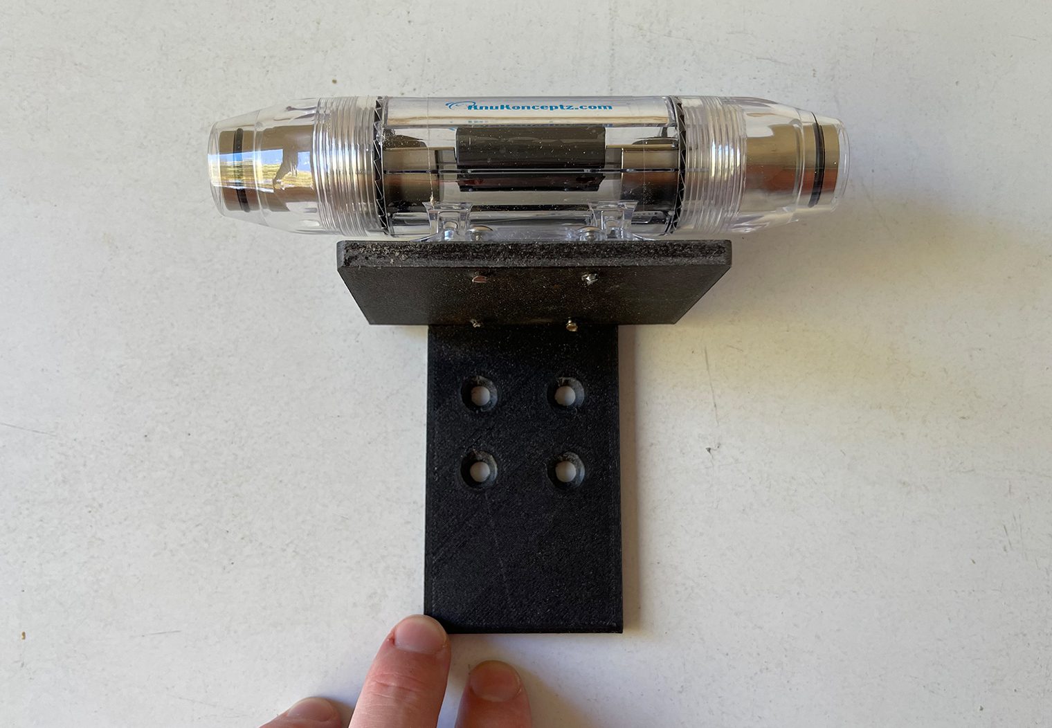
I then mounted the fuse holder to the bracket. Perfect fit and ready to install in the truck!
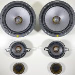
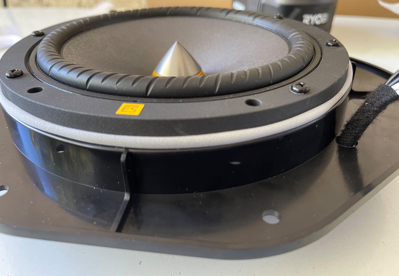
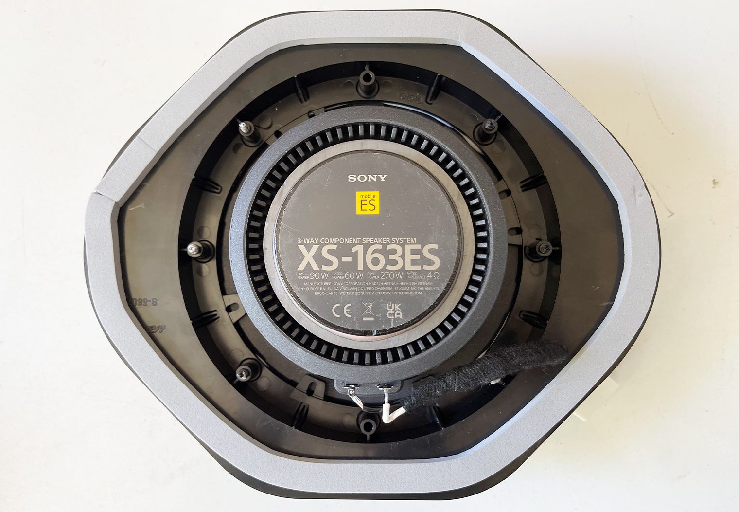
Preparing the Speakers
I also did a lot of speaker prep before I removed the door panels. There are a ton of videos and images of the door panels being removed on the truck if you aren't familiar with it. I knew where the wiring was, how the Metra speaker adapters would fit and install, and so on. But since I designed custom adapters for the tweeters and midrange speakers, I had to remove some of the trim, 3D print my adapters, and test fit everything.
My goal was to have get the speakers to a point where they were plug-and-play. Below are the steps I took to do this. By the time I was completed, I could simply remove the old speakers and tweeters, screw in the new ones on and plug them in!
Custom Tweeter Brackets
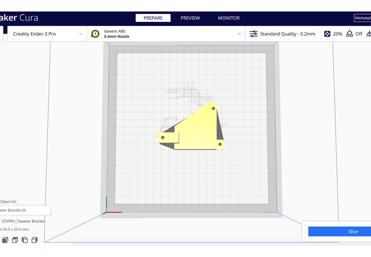
Find these custom tweeter bracket 3D printed files for download here.
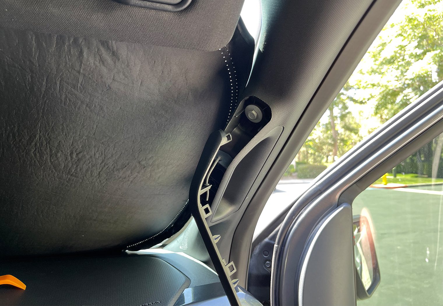
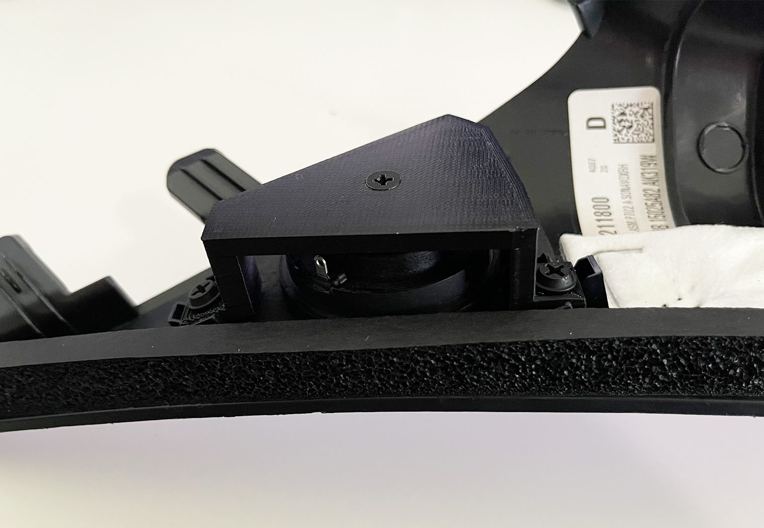
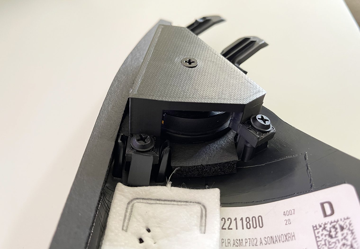
The Sony tweeters that leveraged for this build are definitely larger than the factory tweeters in the A-Pillars. I chose to use the same installation location so that I didn't need to do any custom work to the A-Pillar itself, or any other area of the dash for the new tweeters. But in order for me to use the stock location, I had to go to the 3D CAD drawing board. I designed a custom mount that would use the factory mounting locations (three screws) and adapt them to the Sony tweeter via a mounting screw on the back.
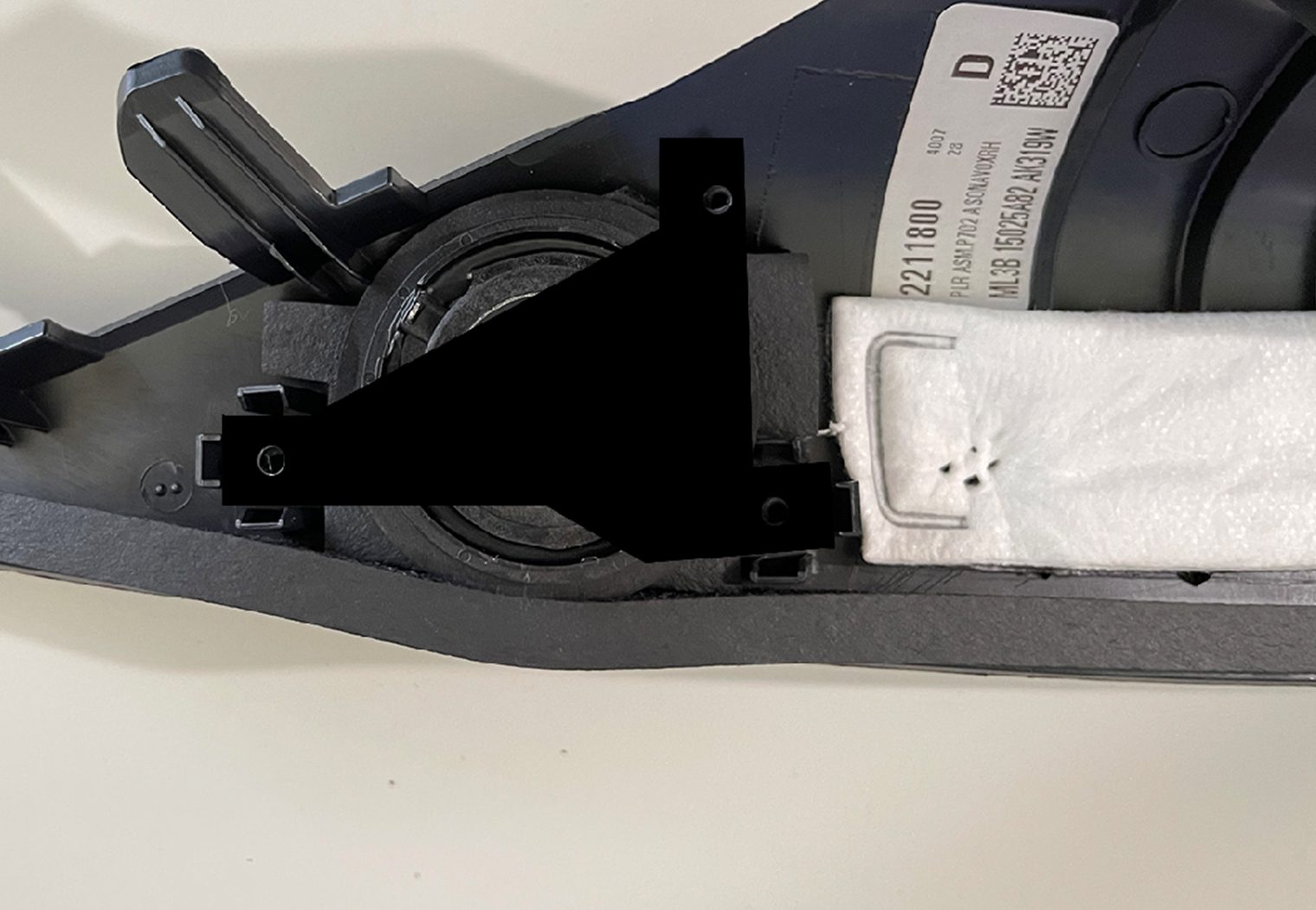
I started out by removing the A-Pillar and factory tweeter so that I could test fit and design the new adapting mount for the new Sony tweeters.
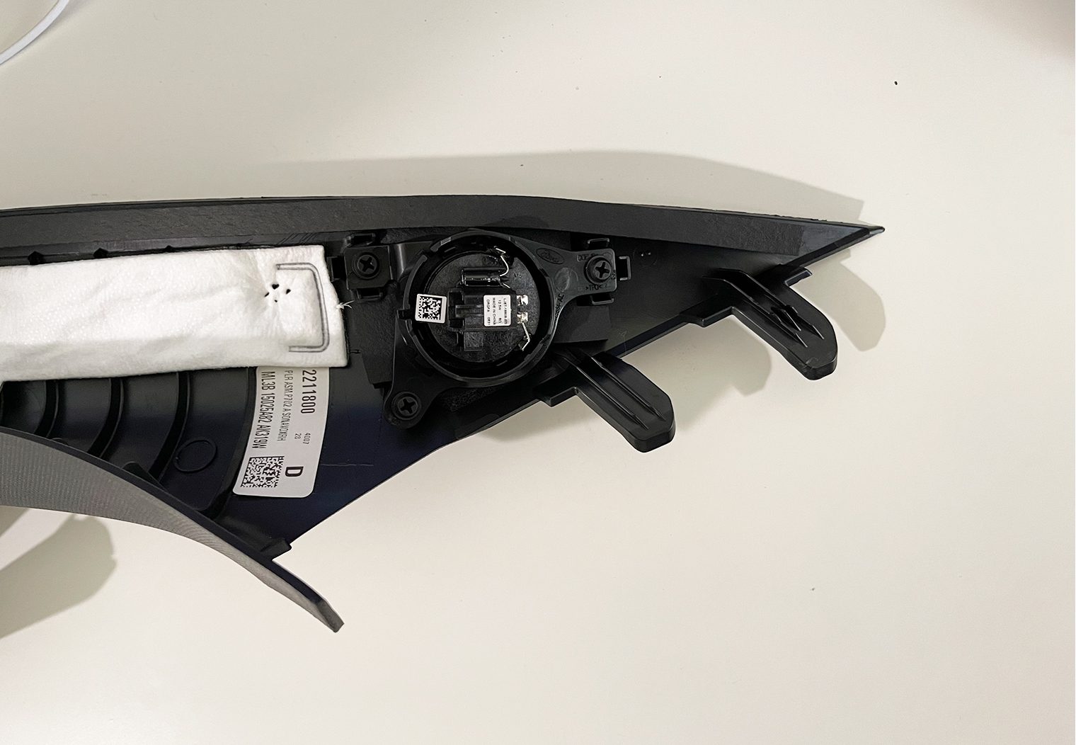
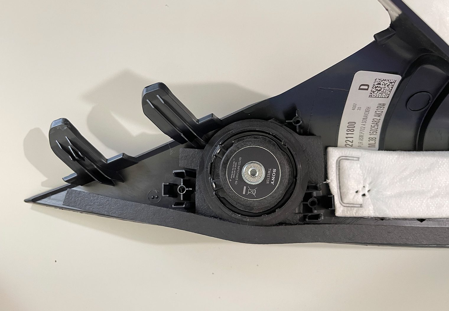
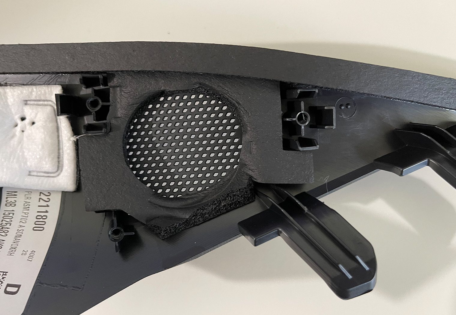
When test fitting the new Sonys, I noticed that the outer rim of the tweeter was too wide for the location so I removed it with a hobby knife.
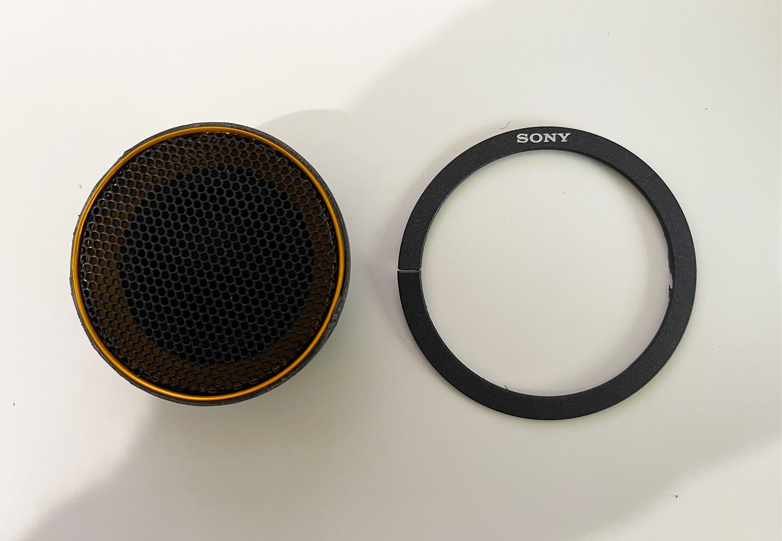
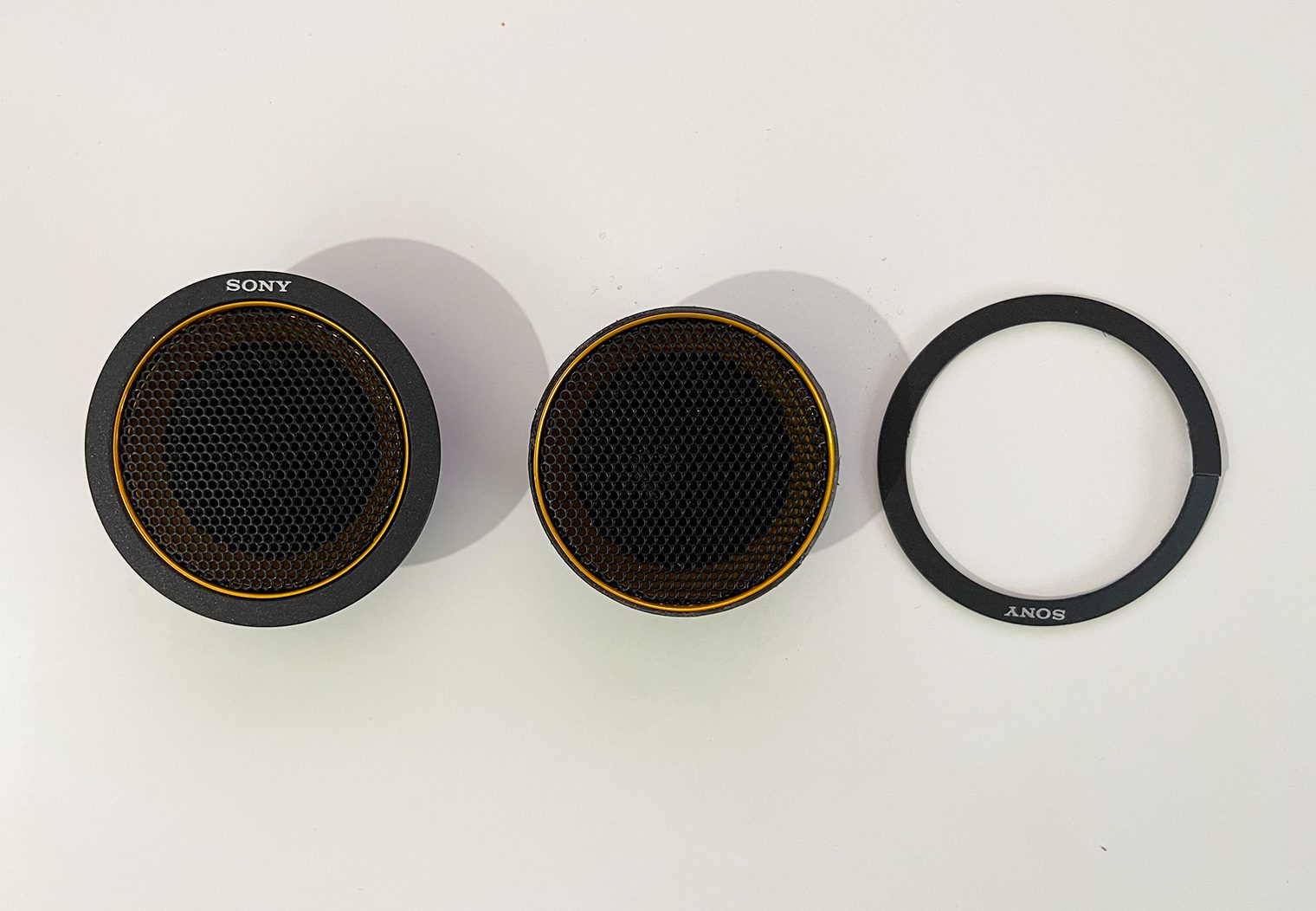
After I removed this outer ring from the tweeter, it fit perfectly in the A-pillar. I went to the design board and printed out my own custom adapting tweeter mounts that would screw directly into the three factory mounting holes in the A-Pillar. Here's a few snapshots of the design process and the final product.
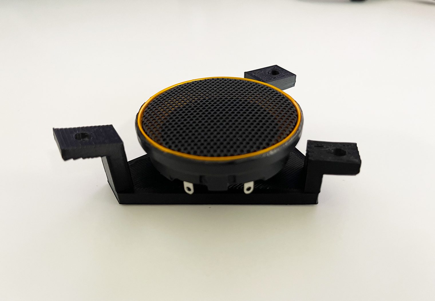
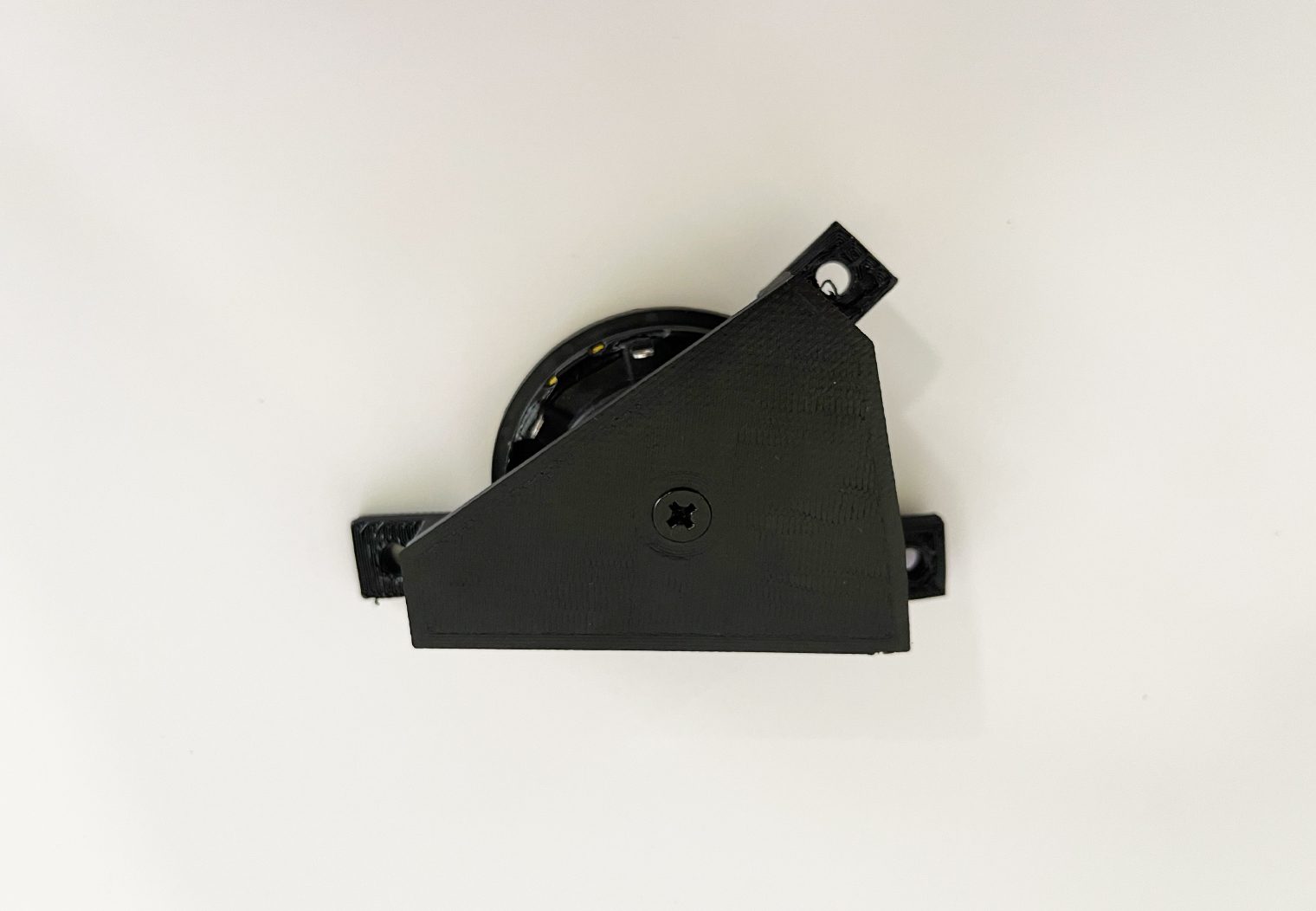
The new adapters fit perfectly in the position of the factory tweeter and screwed straight into the A-Pillar. Here's a few snapshots of the final product.
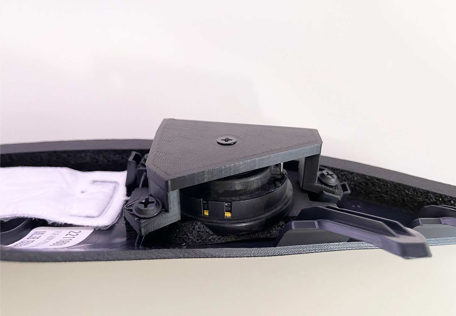
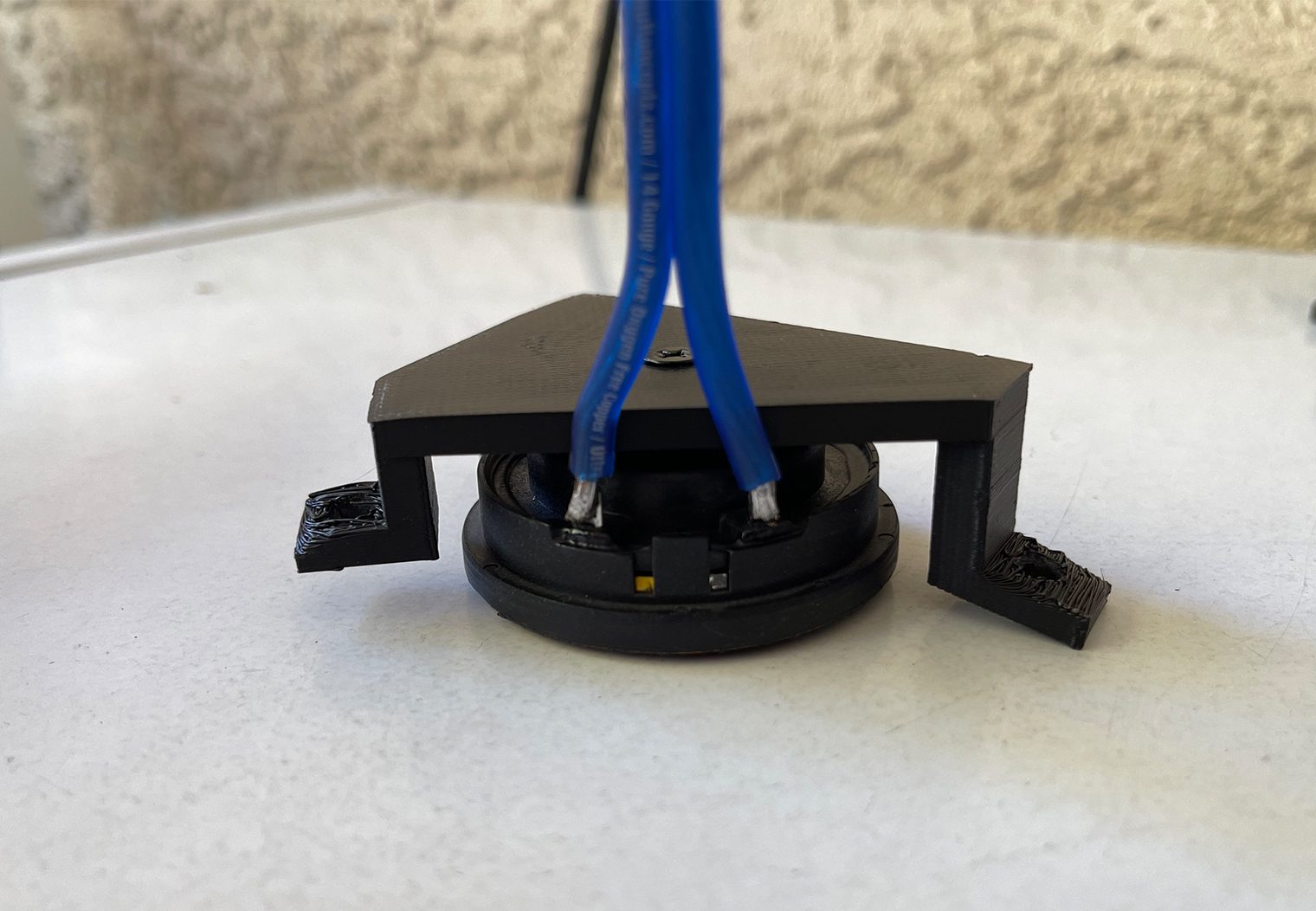
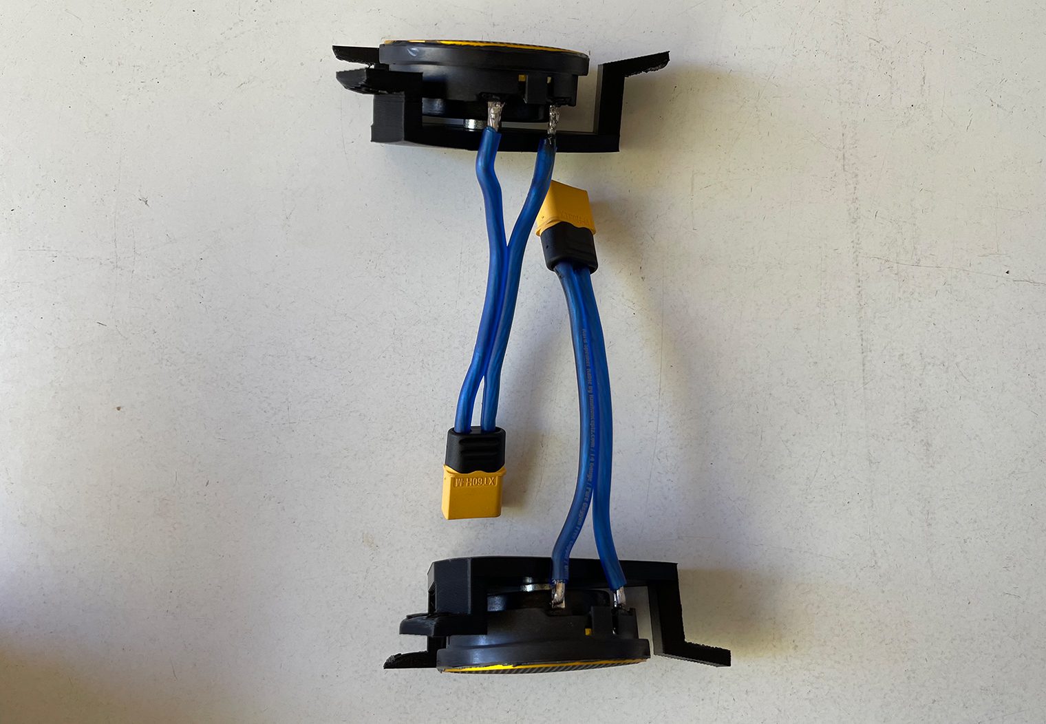
Once I had the tweeter mounts completed, I could continue with wiring the tweeters. This was pretty simple – I used two XT60 plugs and soldered them to some speaker wire. Then, soldered the speaker wire to the tweeter terminals. The end result would allow me to simply unscrew the old tweeters, screw the new ones onto the A-pillar and then plug them in to the new speaker wire that I planned to run to both A-pillars.
Custom Center Dash Midrange Adapter
Find this custom midrange adapter plate 3D printed files for download here.
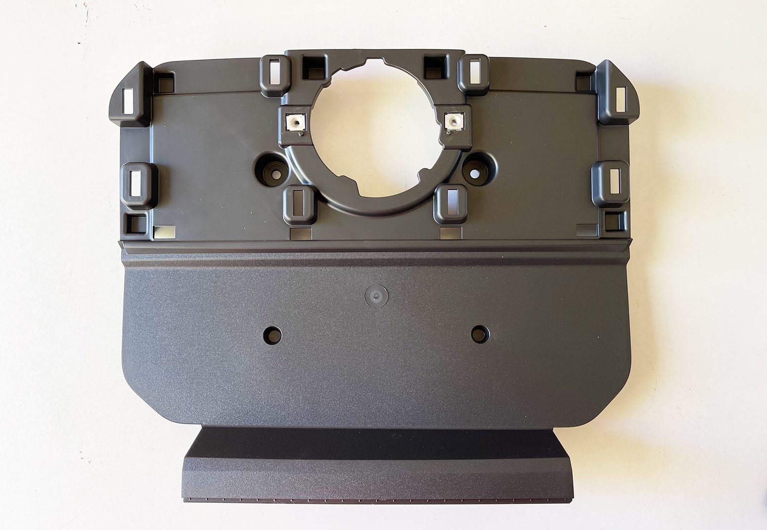
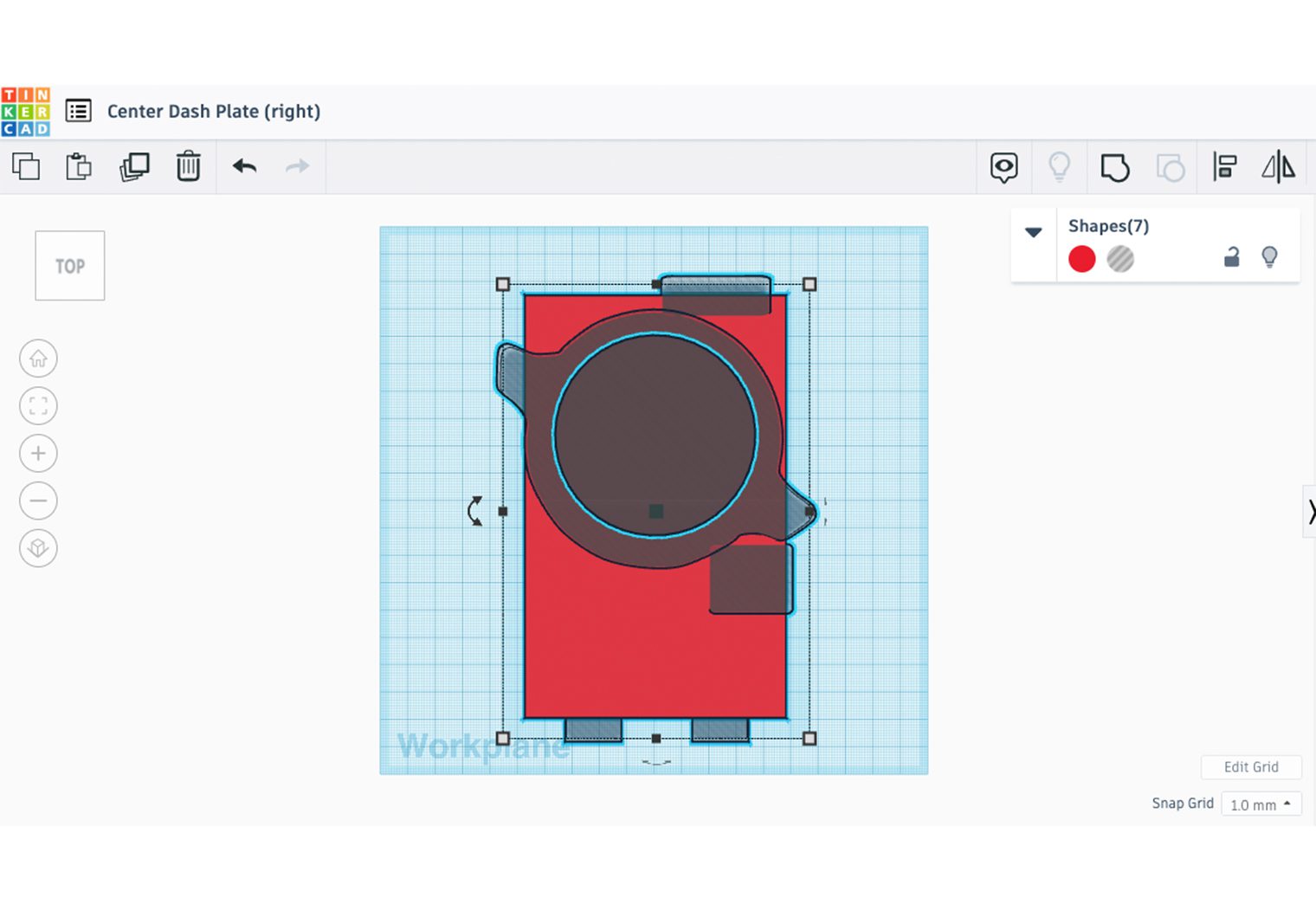
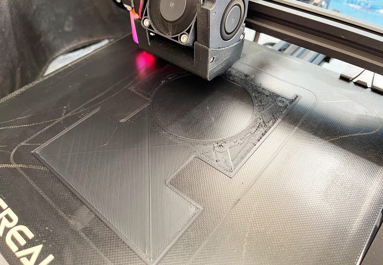
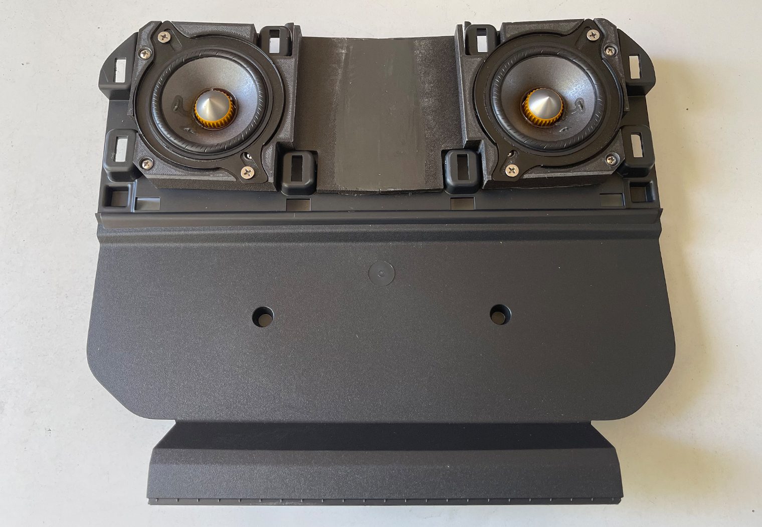
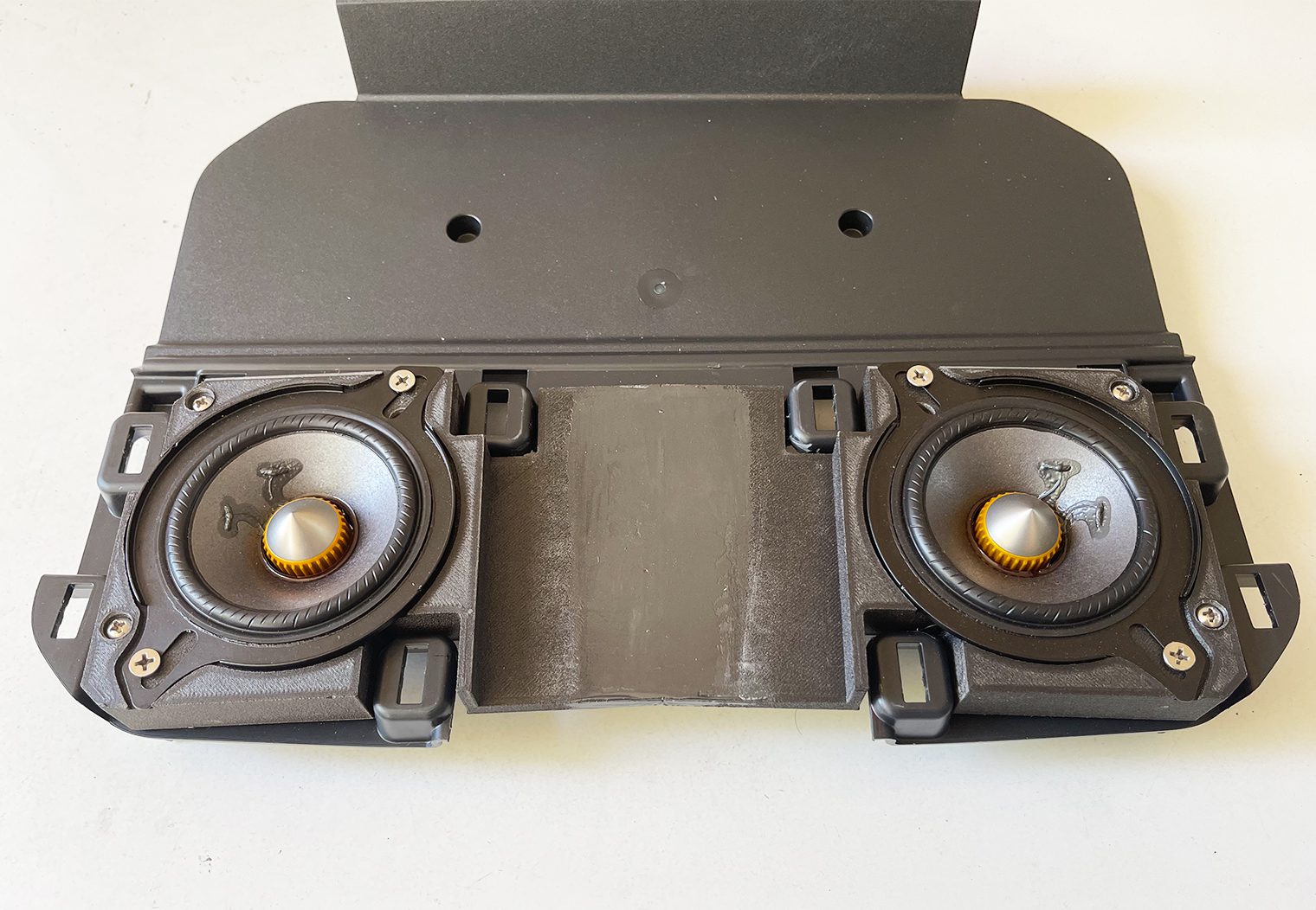
This was probably the most challenging design I had to make via the 3D printer. There were a lot of variables I had to consider in order to place two 3 1/2″ midrange speakers in the factory dash location where the single 3 1/2″ midrange once lived. Depth, height, speaker positioning, wiring – all of this had to be considered in order for me to put two 3 1/2″ speakers where only one was designed to live. I was pretty determined to fit them both below the factory grille that sits on the dash so that it looked stock too.
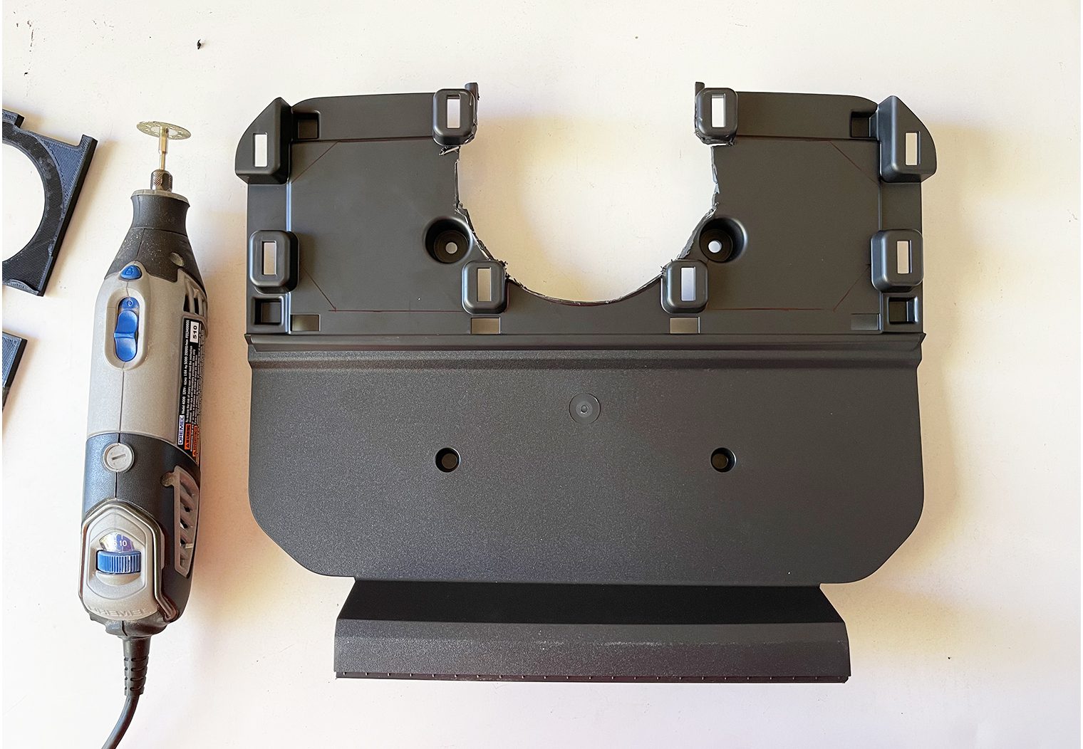
I started by purchasing a second dash-mounting plate (part number ML3Z-1504338-BC). I knew this was going to take some time and I didn't want to have my truck torn up for days while I designed and test fitted the new mount. Once I had the new factory mounting plate, I went to work cutting, printing, and test fitting my custom 3D printed mount.
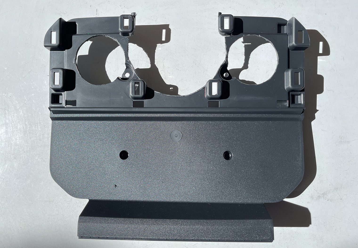
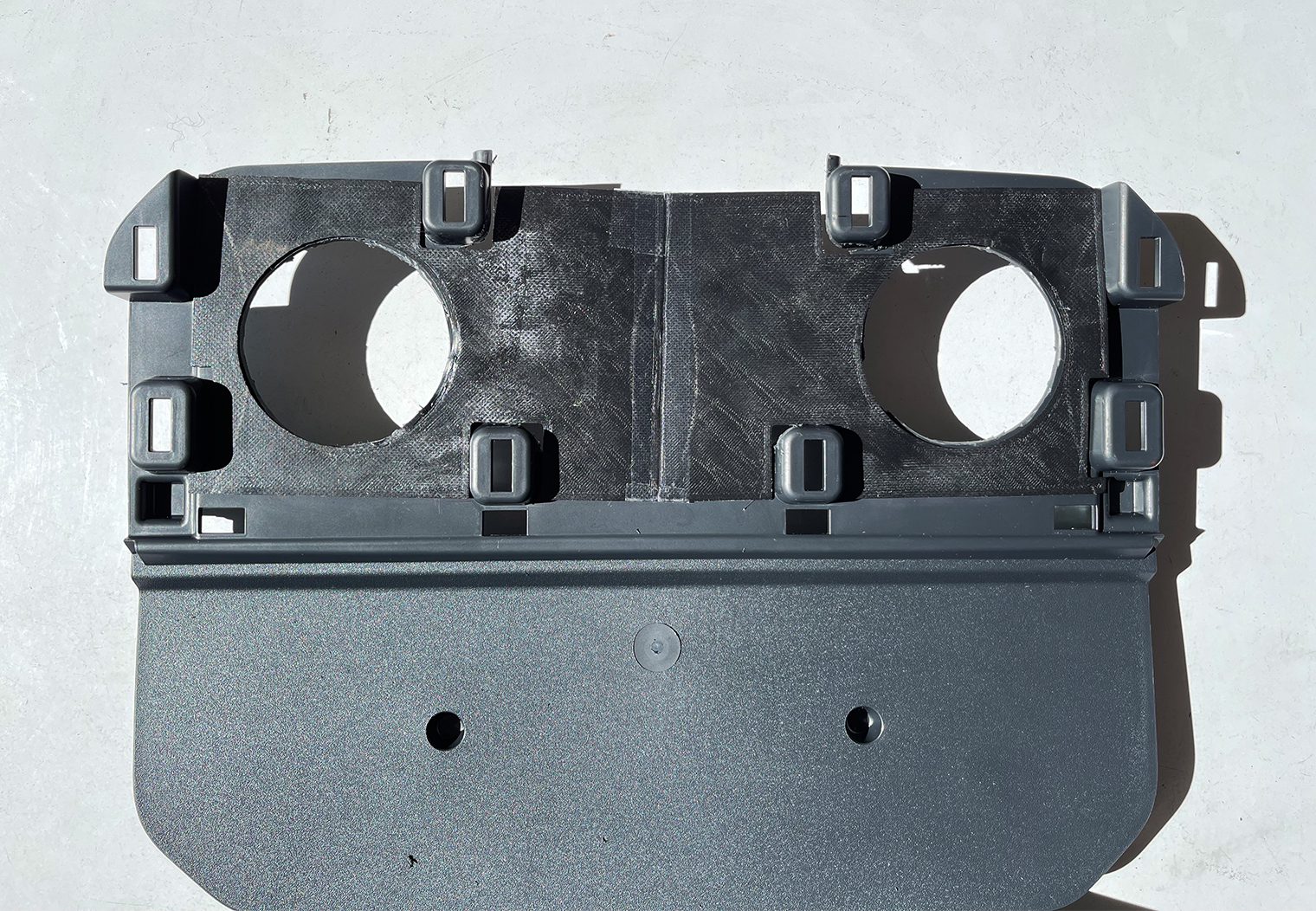
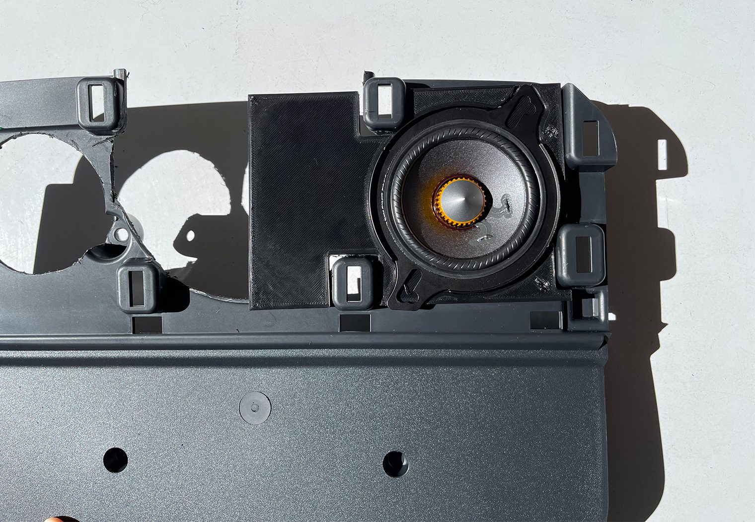
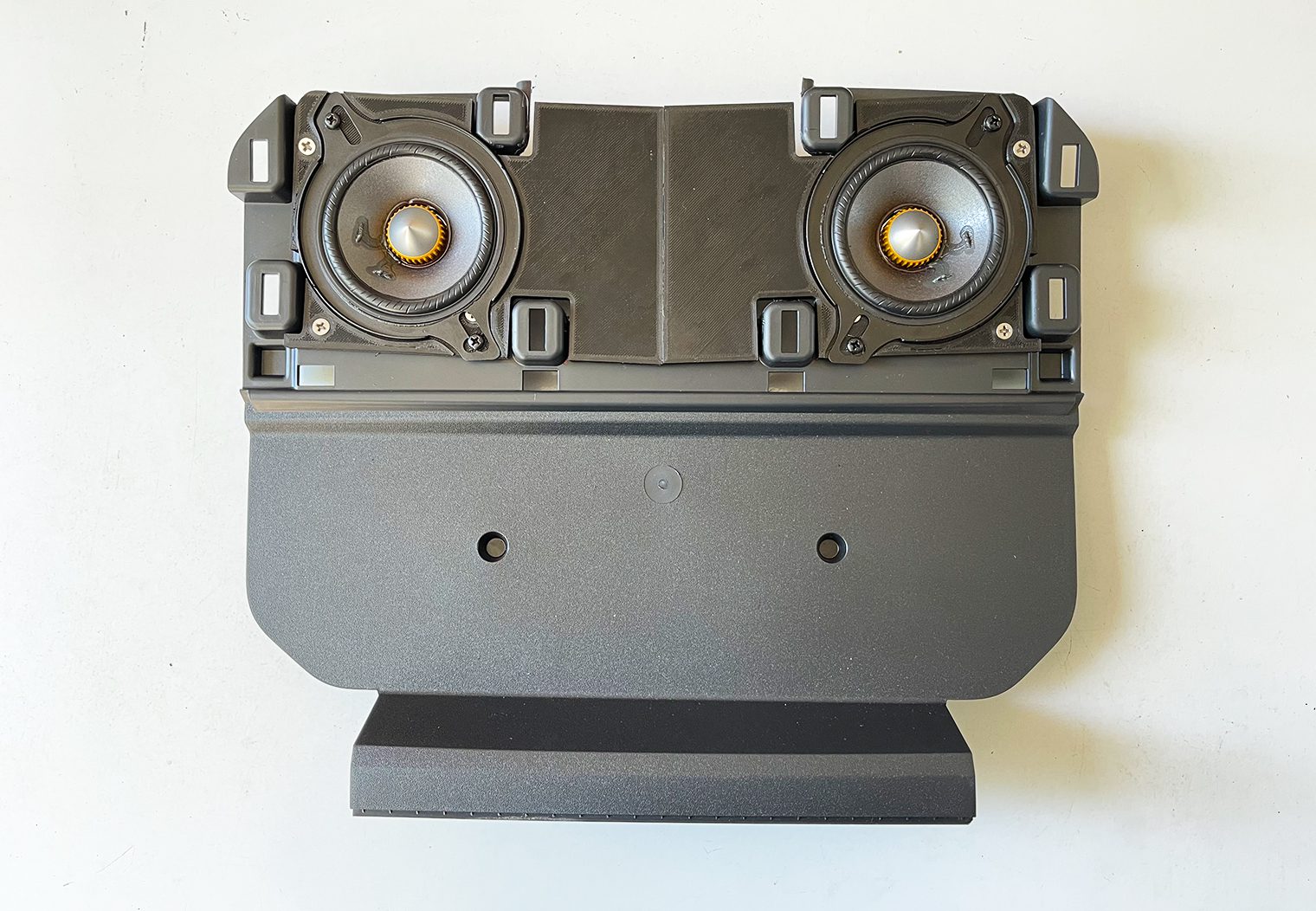
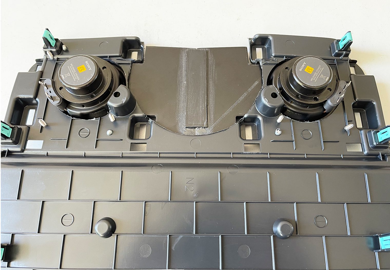
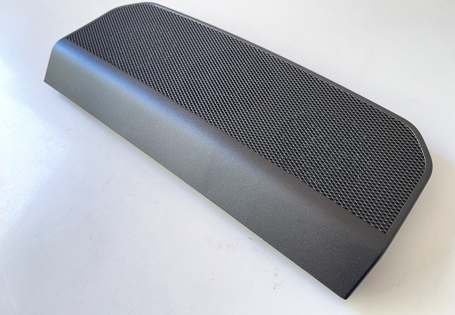
The final product came out very clean and fit perfect in the factory location of the dash. The covering grille/trim piece even fit flush on top of the speakers, giving it a nice factory look. You would never know that there were two custom-mounted midrange speakers here. And the best part is that, besides the factory speaker plate, I didn't have to cut or modify anything in the dash to make this fit. If I wanted to remove these speakers and put the factory one back in, it would be a direct swap with the old speaker and factory plate.
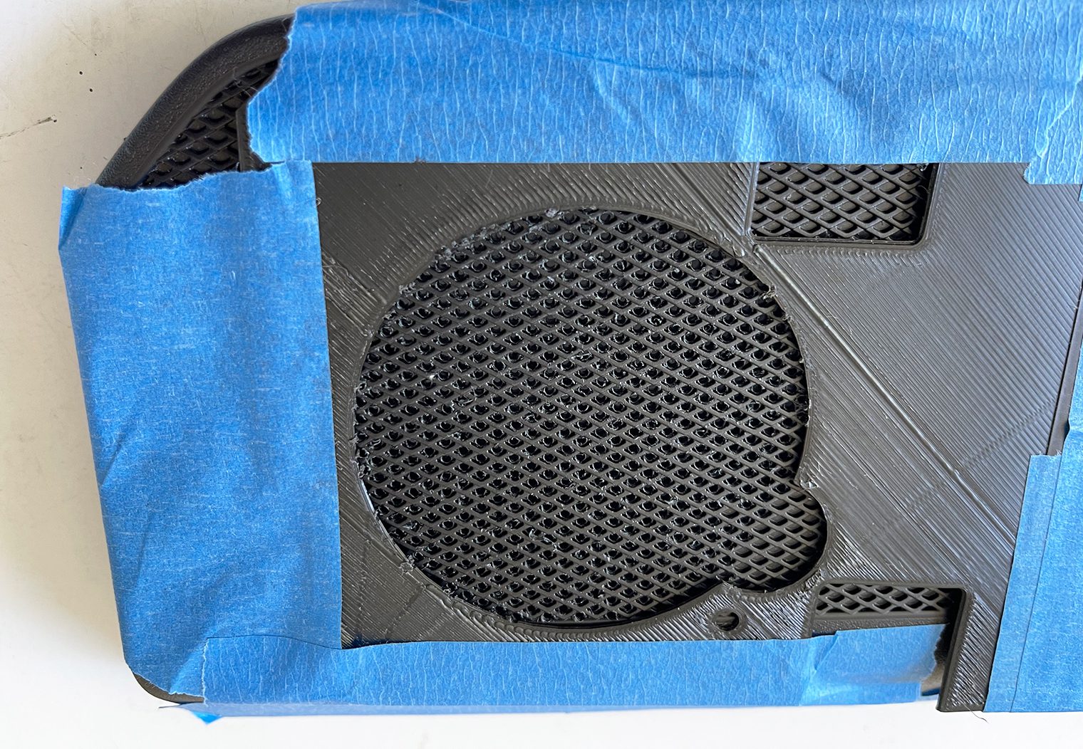
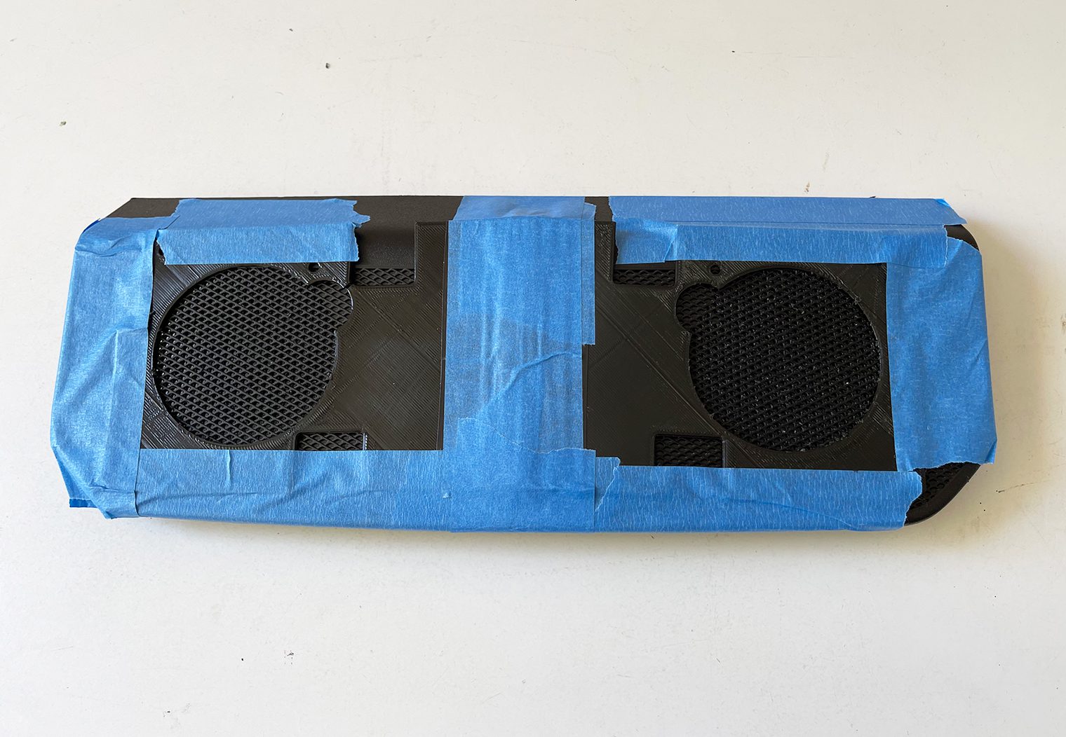
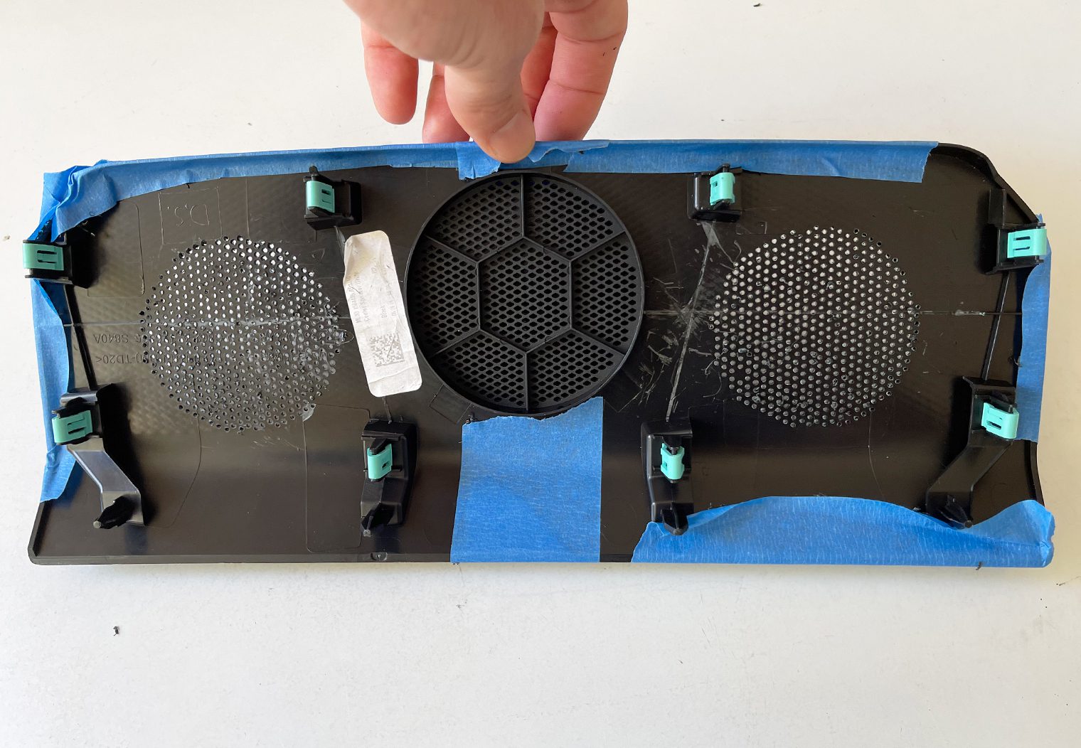
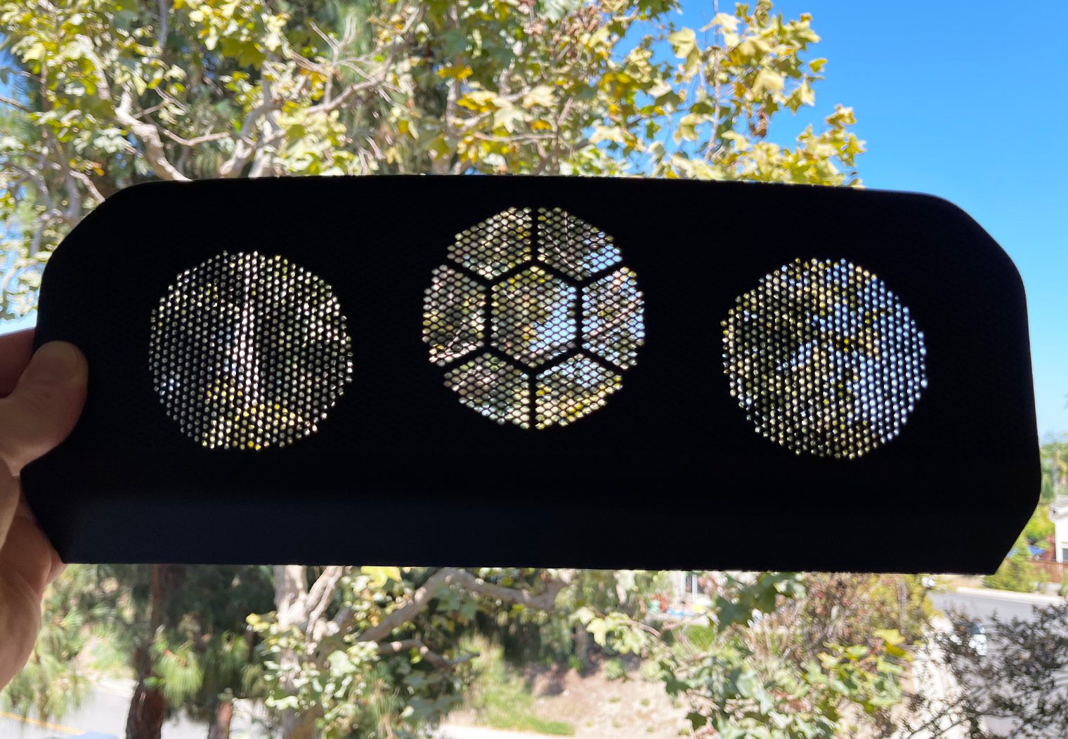
The final step to this custom midrange setup was to modify the covering grille piece. Out of the factory, there are holes at the center of the grille to allow sound to escape from the factory midrange speaker. The problem was that these holes were at the center of the grille so if I didn't modify it, the new Sony speakers would be playing into the back of a piece of plastic.
So I had to drill out holes in the factory grille where the new speakers were placed to allow sound to pass through the grille. I did this with a drill bit and drill, using a template that I created based on the dimensions of the adapter plate to guide where I drilled holes. Nothing fancy, just a lot of time and patience!
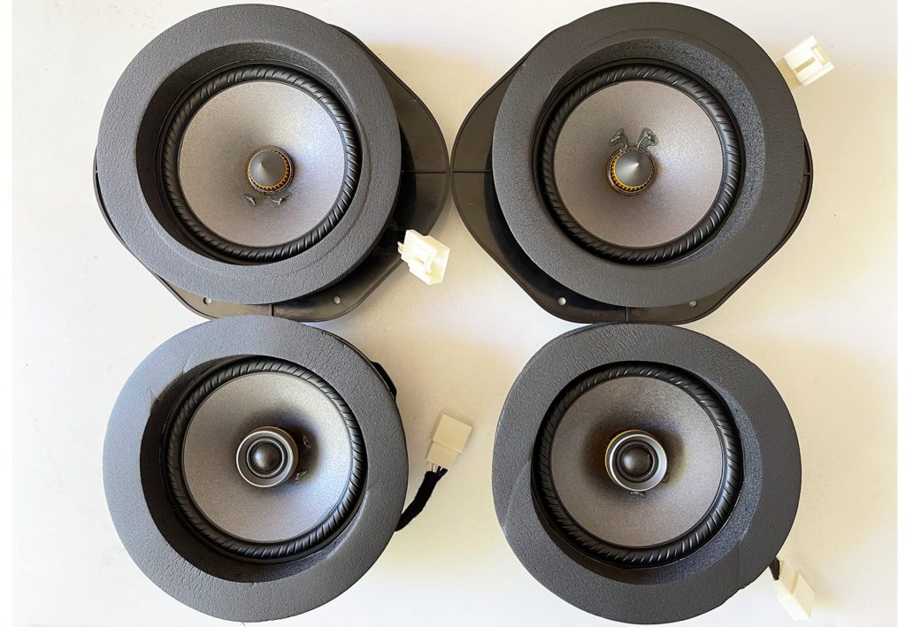
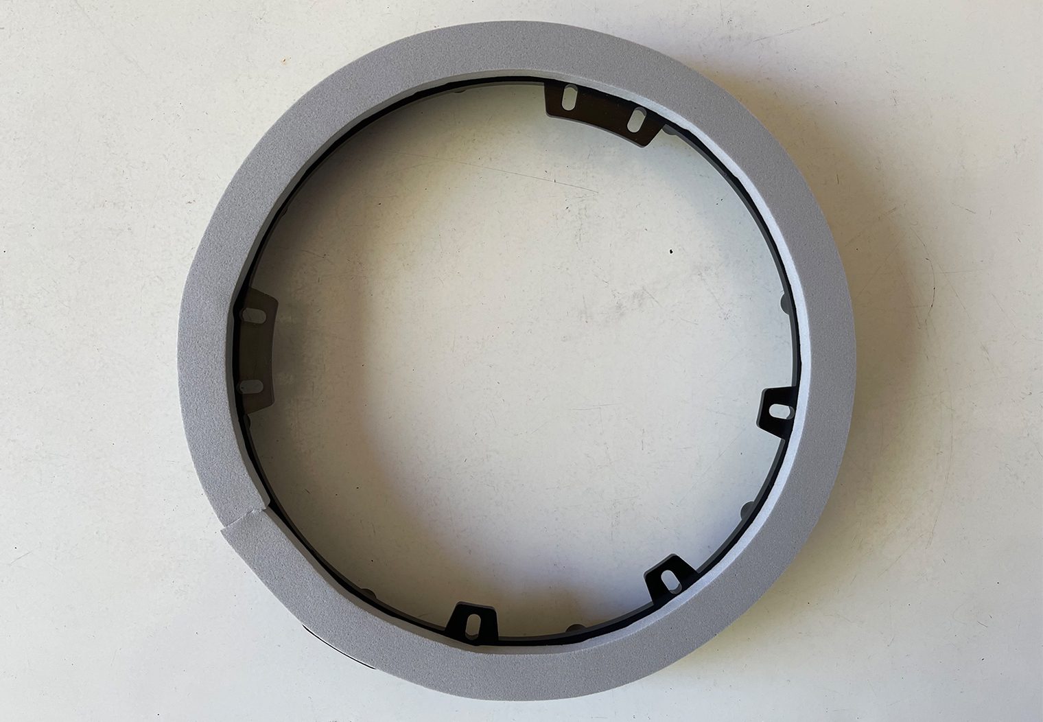
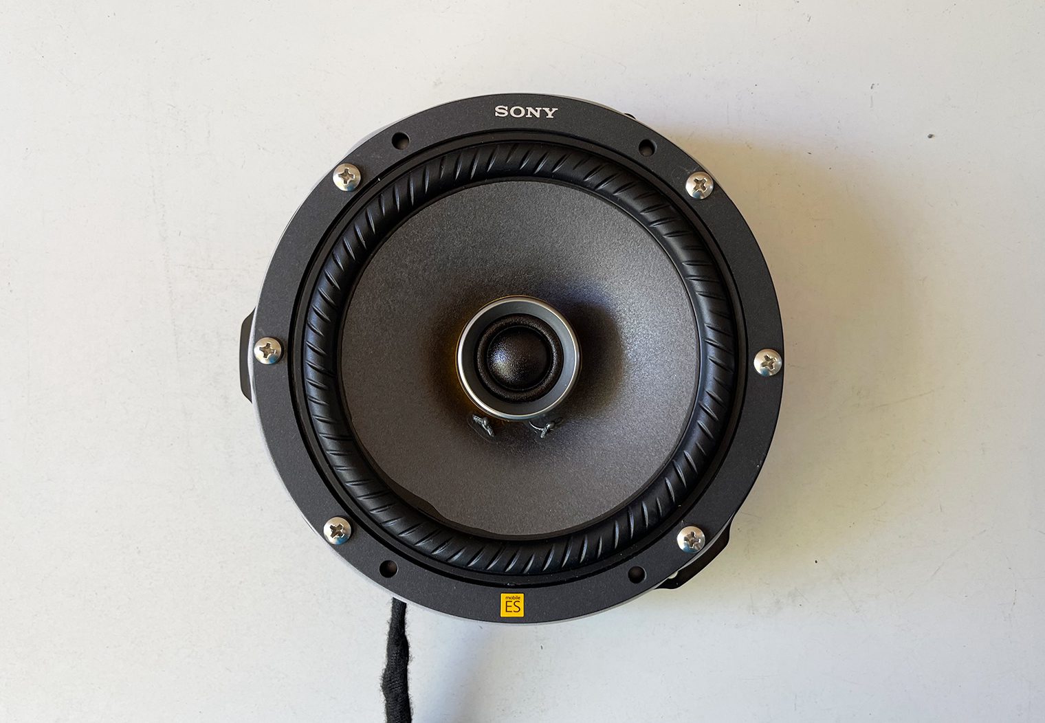
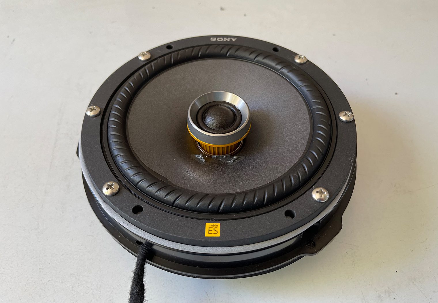
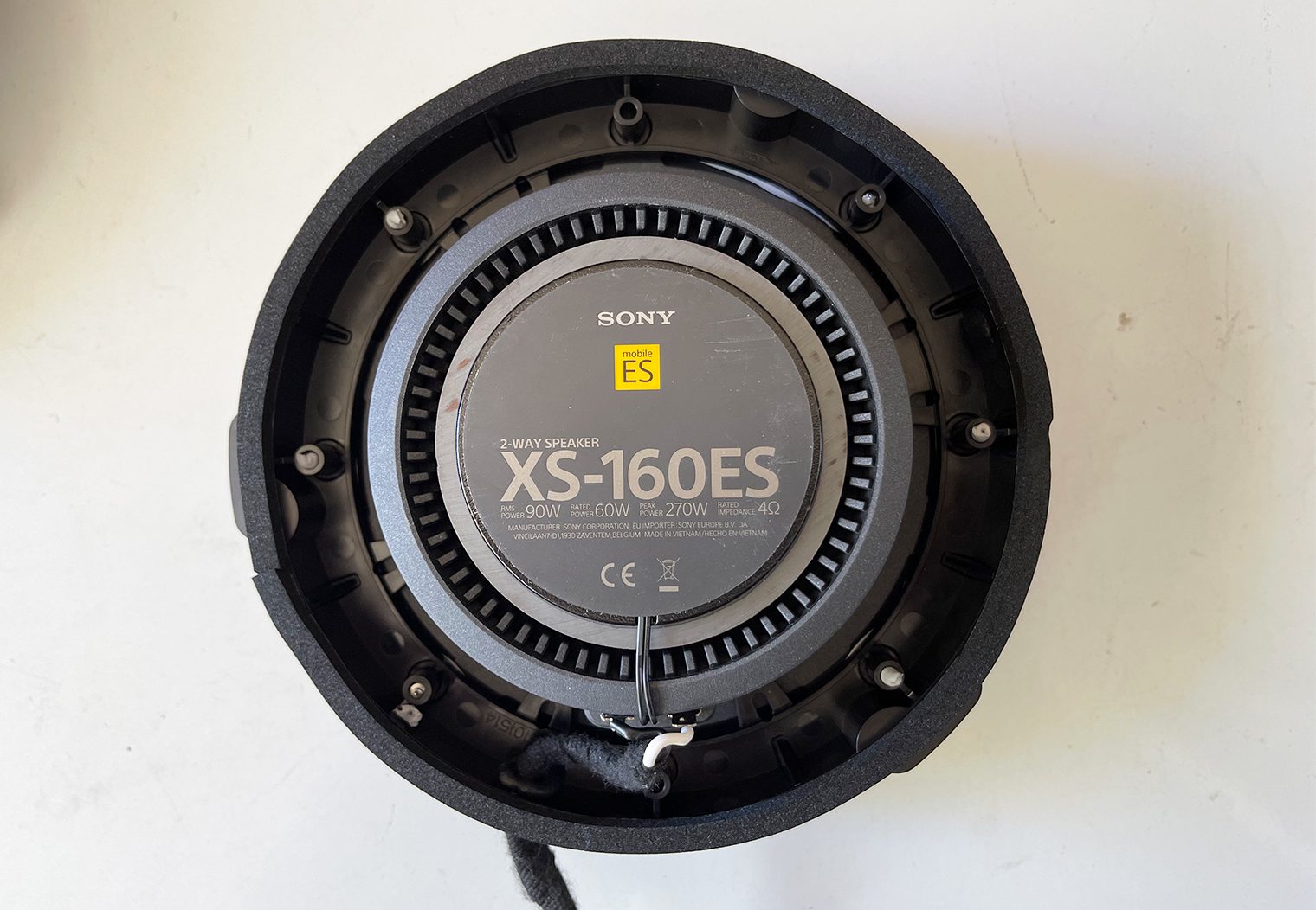
Pre-wiring and Mounting the Speakers/Adapters
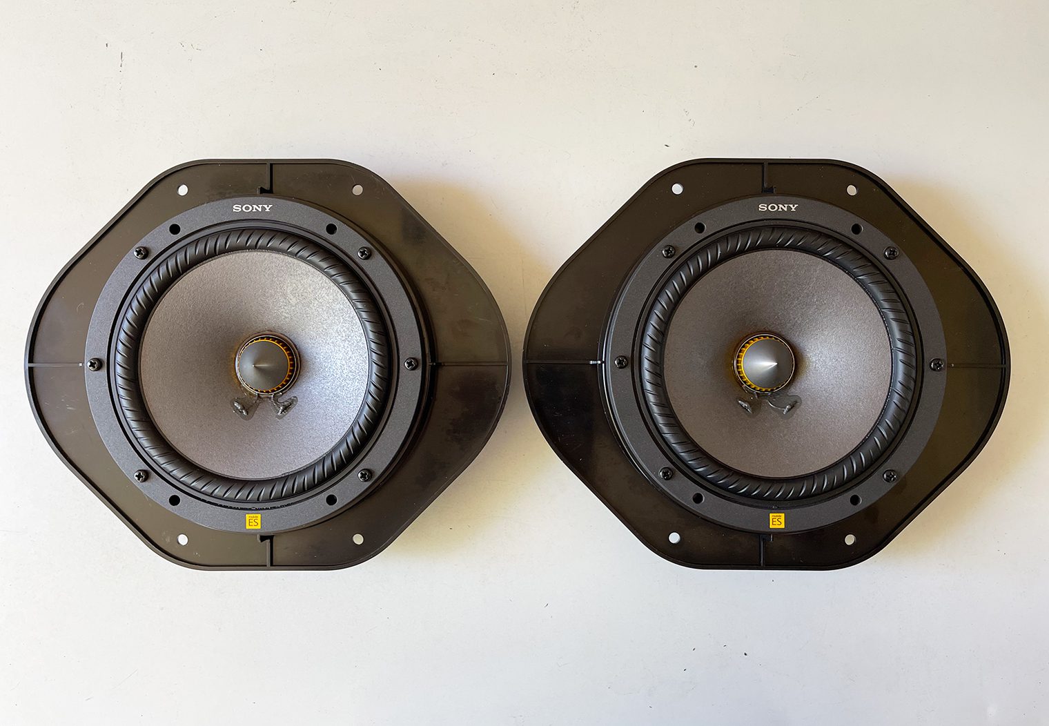
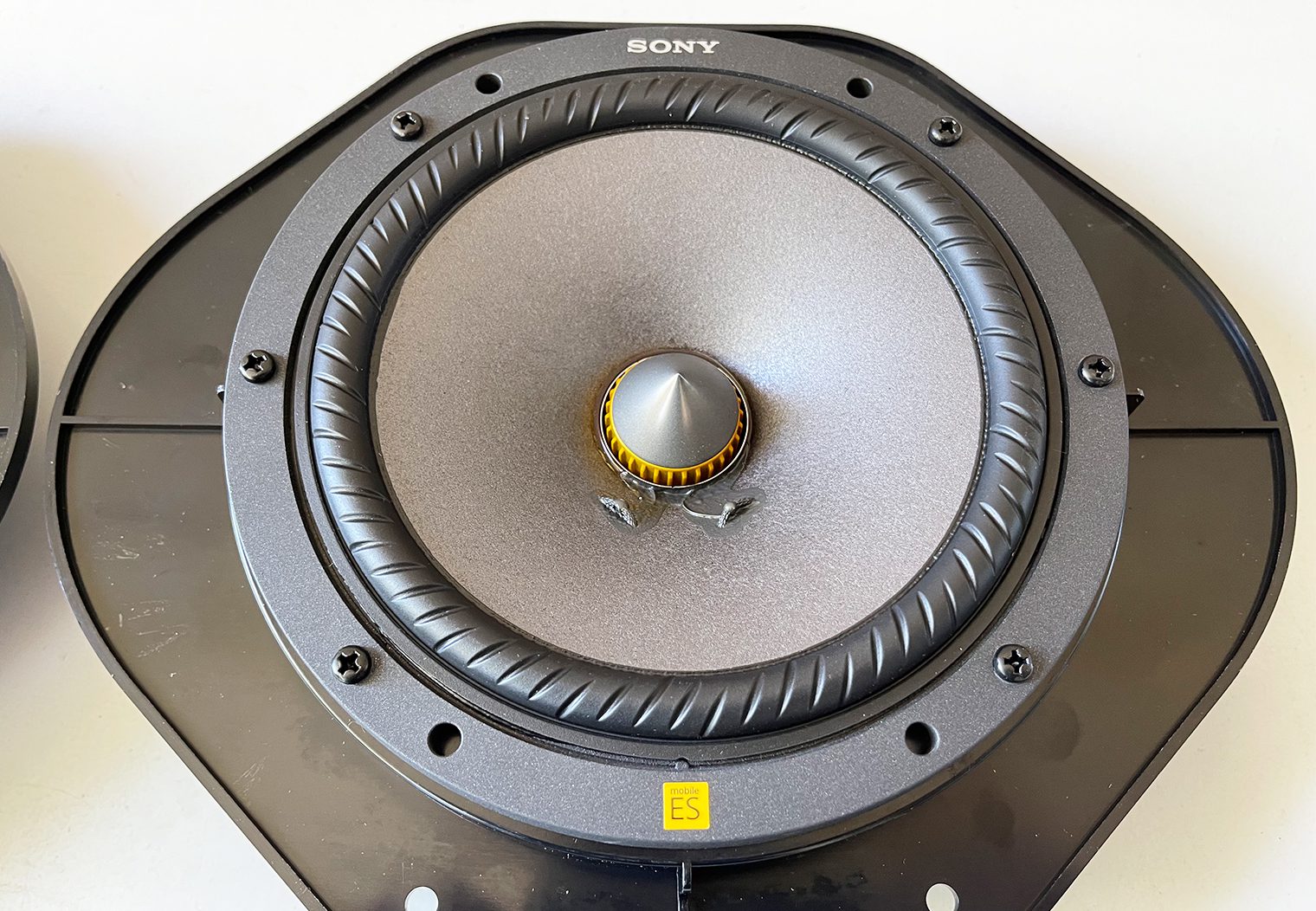
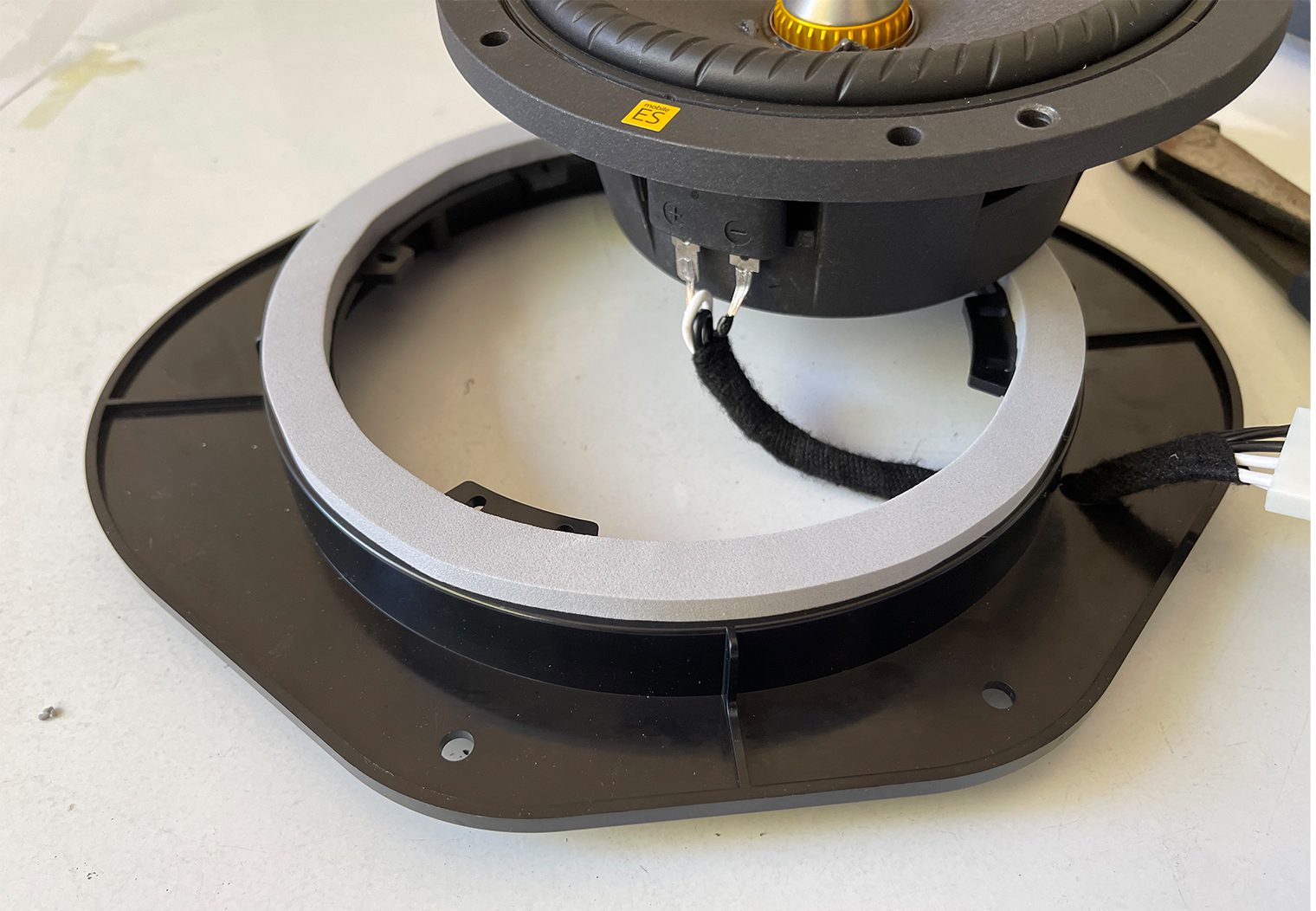
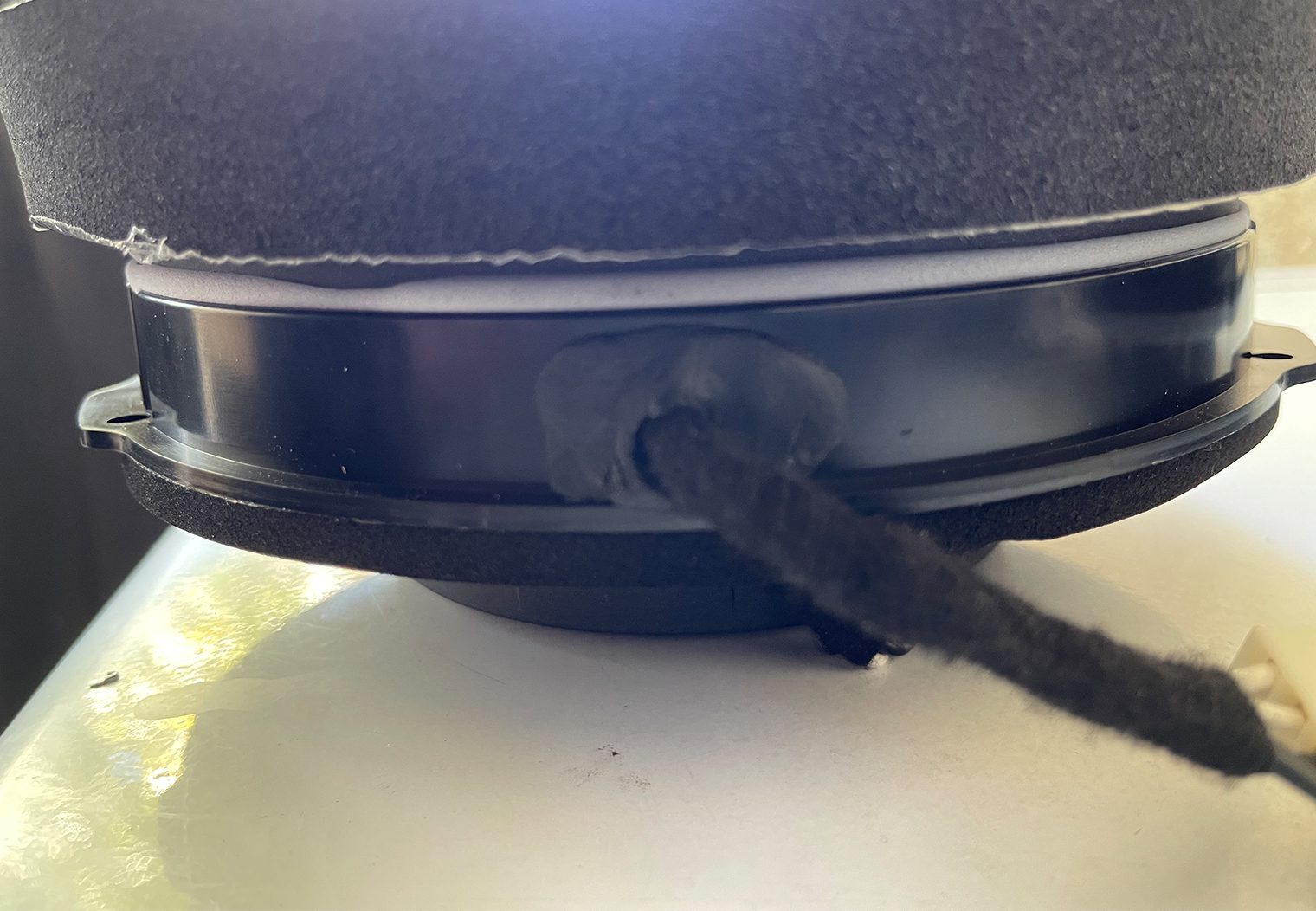
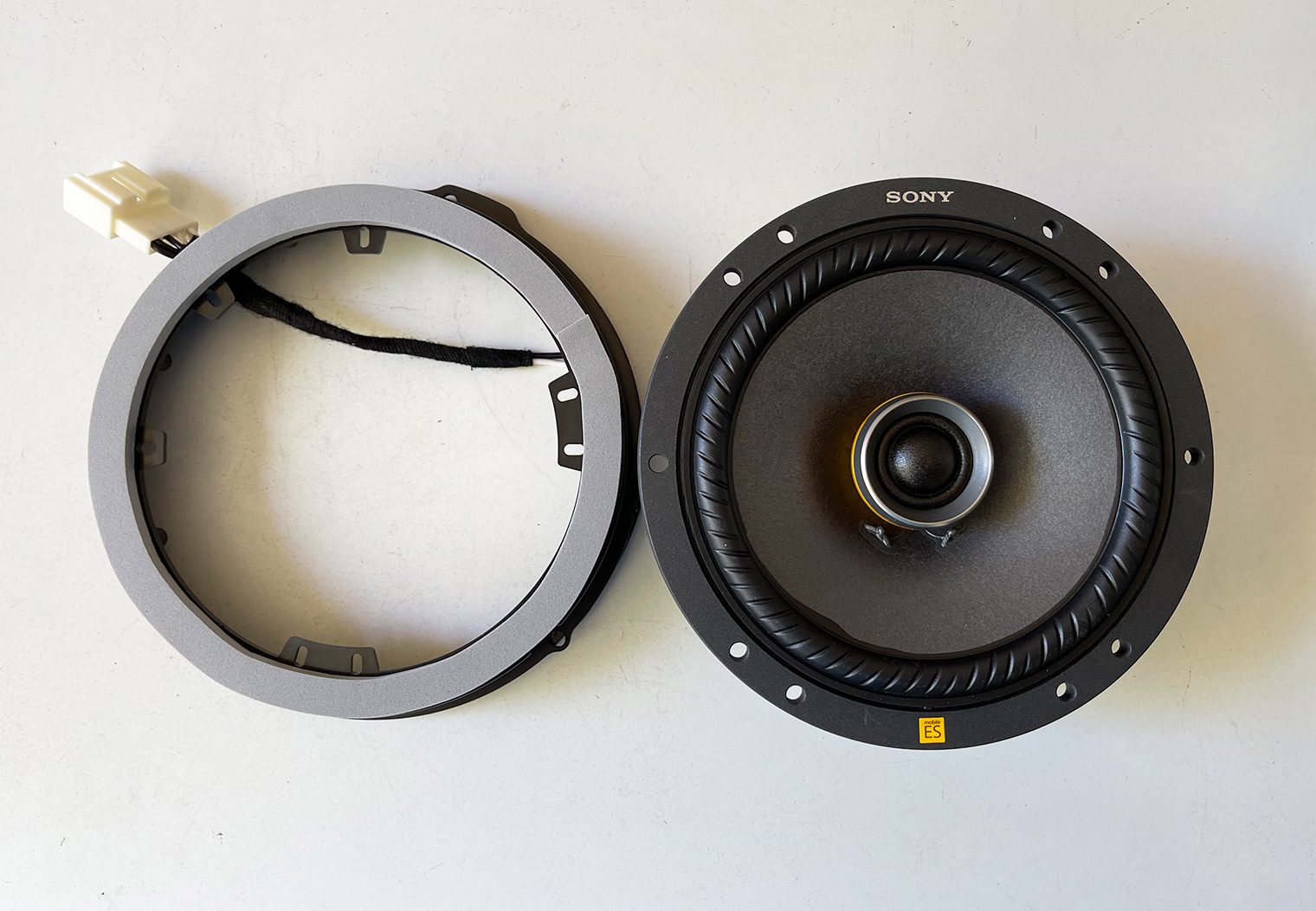
After all of my speakers were mounted to their adapters, test fitted and so on, I could then begin the process of pre-mounting and pre-wiring them so that when I was ready to install everything, they would simply mount up and plug in.
This included leveraging a combination of Metra adapters and adapting plugs, along with my own XT60 plugs. I also used speaker/sound tape and foam to reduce unwanted resonance and better seal the surfaces between the face of the speaker and the door panel.
Front Door Speakers
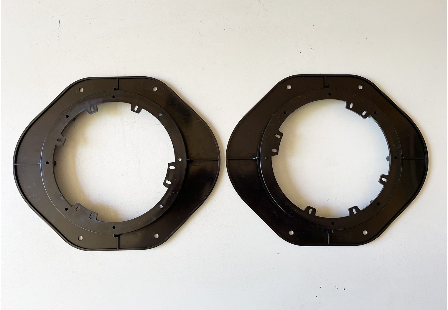
Rear Door Speakers
Building the Amplifier Rack
In part one of this install series, I showed the location that I was going to place the amp rack (behind the rear seats), along with some of the preliminary measurements and material that I chose to use (HPFE board). Now that I knew the location and had an idea of where/how I was going to fit the custom amp rack, I was able to measure, cut and prep the amp rack for installation.
Creating a Template & Cutting the HPFE to Size
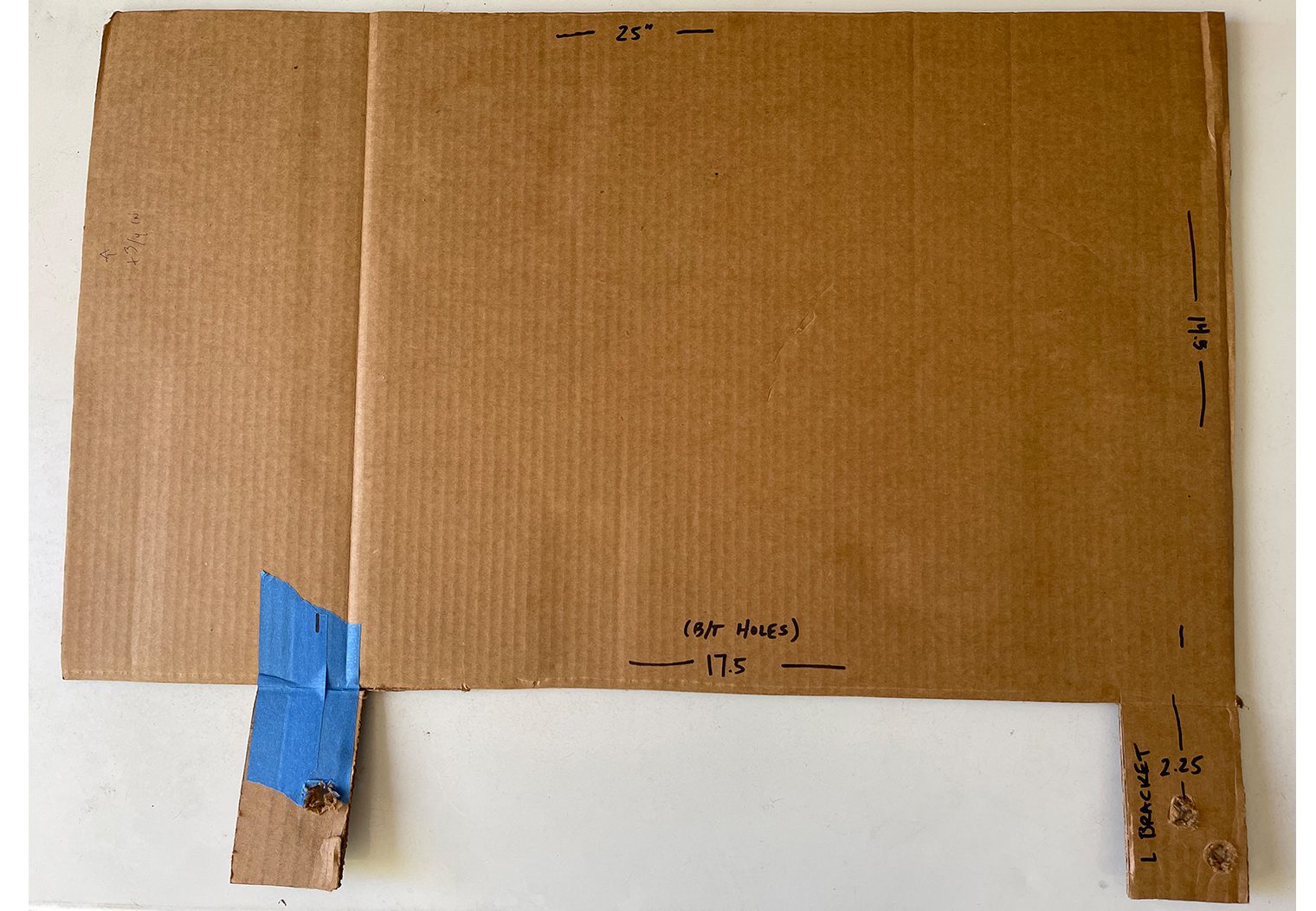
First thing that I did was create a template. This would allow me to create precise measurements for my amp rack, including where it would mount/secure to. When I create templates like this, I always like to use double-walled cardboard. You could measure manually too, but my preference has always been to create a template for large areas like this. So that's what I did.
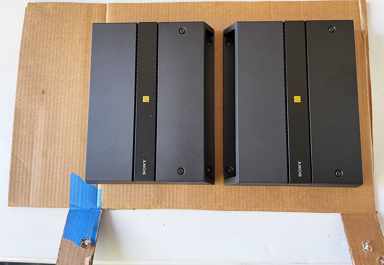
I created the template and then started to test place some of the products to ensure that it would fit.
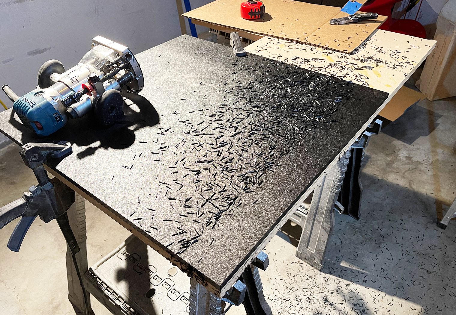
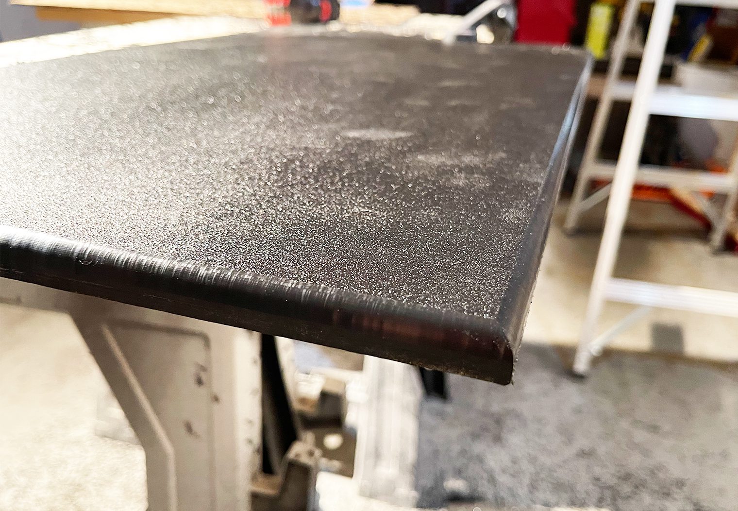
After I had all of my measurements, I cut the HPFE board to size. I used a router and a spiral flush trim bit to cut it. The HPFE is super soft and easy to cut and this gave me a very clean edge without the need for a table saw. I also used a roundover bit to round the corners so that they weren't as sharp and give it a finished look.
Custom L-Brackets
Separately, with the amp rack template created I also was able to account for the location, size and position for custom L-brackets that would secure everything to the truck. I chose to use the factory rear seat mounts to secure the brackets to. The seat bolts are heavy duty, and were perfect for securing a heavy rack like this to. I used my micrometer to measure the the distance to the bolt, the diameter of the bolt, width of the bracket and etc so that I could purchase a custom bracket.
Using MiSUMi's configurable L-bracket tool, I entered all of my dimensions into their webtool and ordered up. These weren't cheap by any means. I spent around 40$ for L-brackets. But by building my own custom brackets, I could ensure that they were fitted, sturdy and look like they fit the application as well.
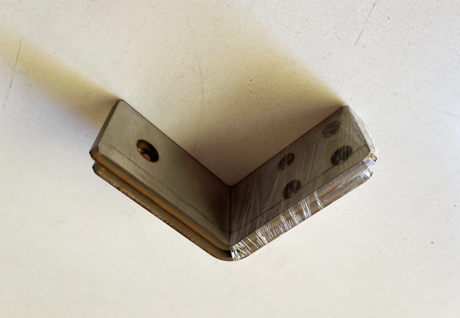
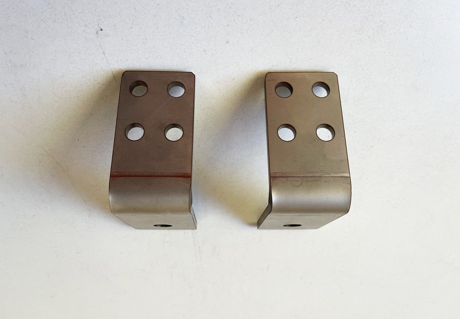
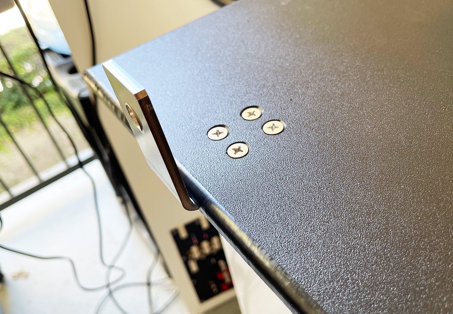
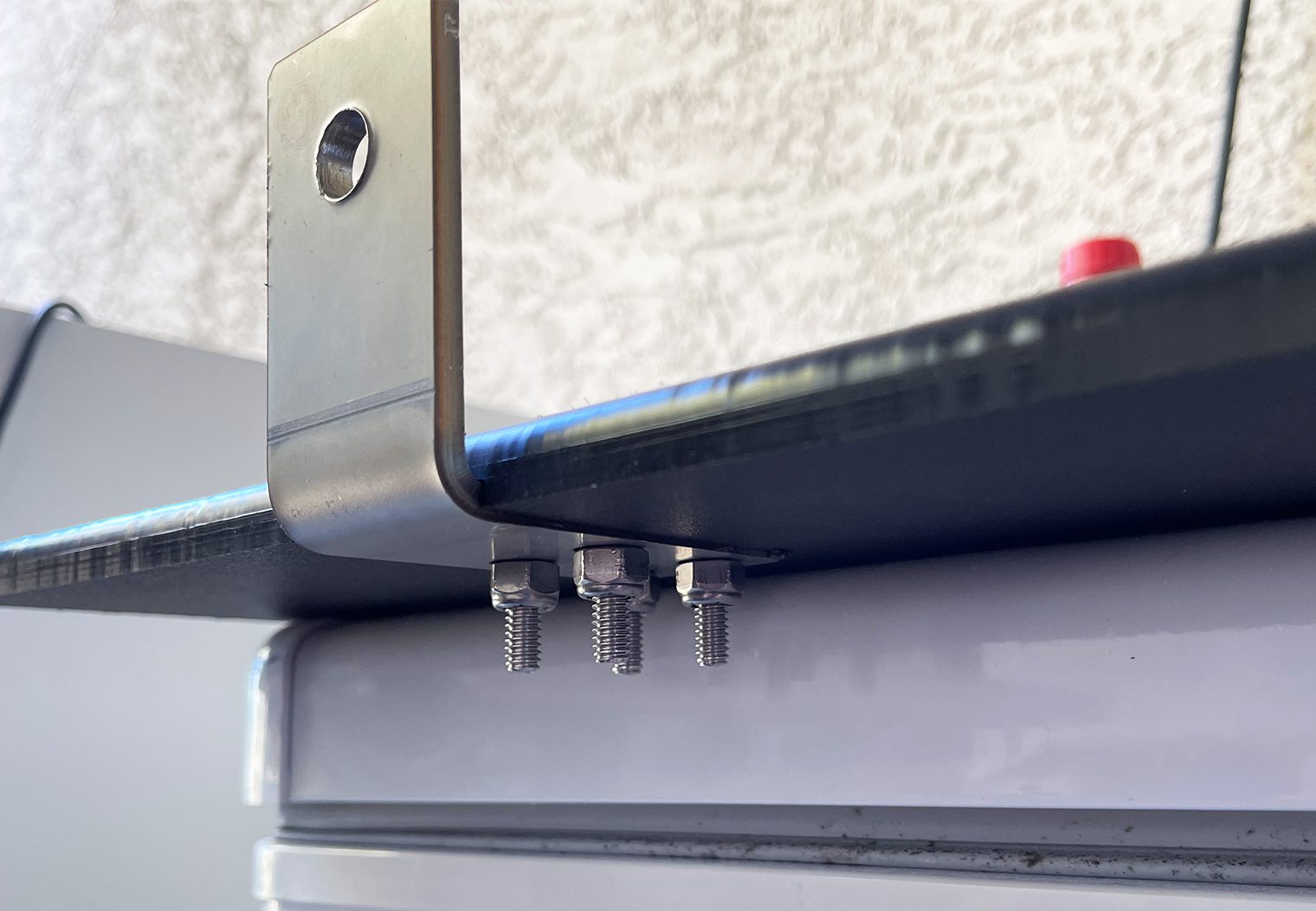
The end result was perfect! I counter sunk them onto the backside of the amp rack and mounted them up!
Mounting & Wiring the Amps
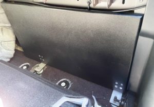
With amp rack cut and the custom L Brackets mounted, I was able to test out the fitment of the amplifier rack in the back of the F-150. I did this before I started to drill and mount the amplifiers, wiring and etc. The most important aspect I was looking to validate was the distance between the two L-Brackets so that they would slide onto the existing rear seat bolts. There was very little clearance, but my measurements proved correct – the amp rack fit perfectly into the space, tucked along the bottom half of the rear wall of the cab. The spacing between the L brackets was perfect too and easily fit onto the factory bolts in the floor.
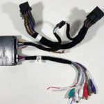
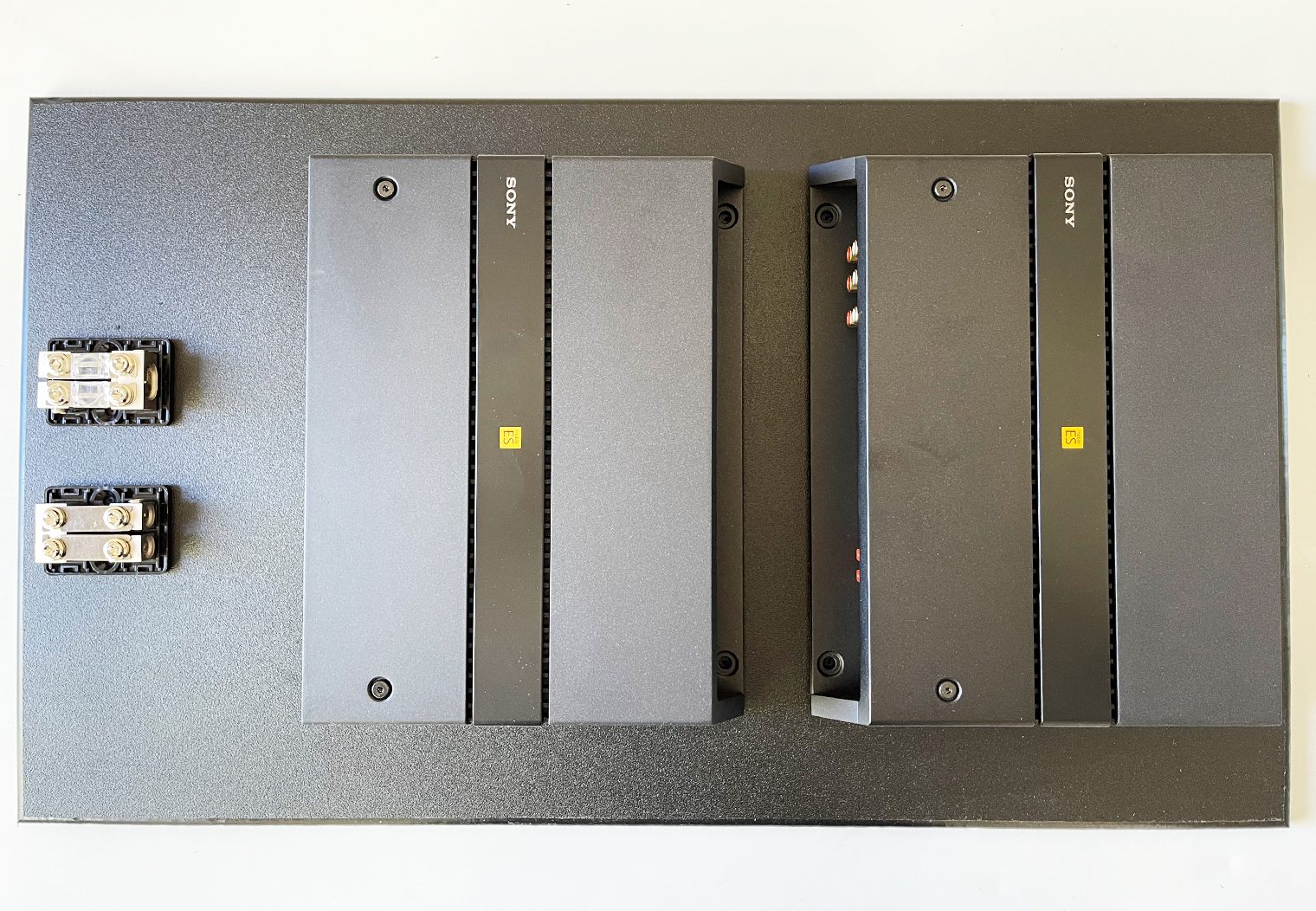
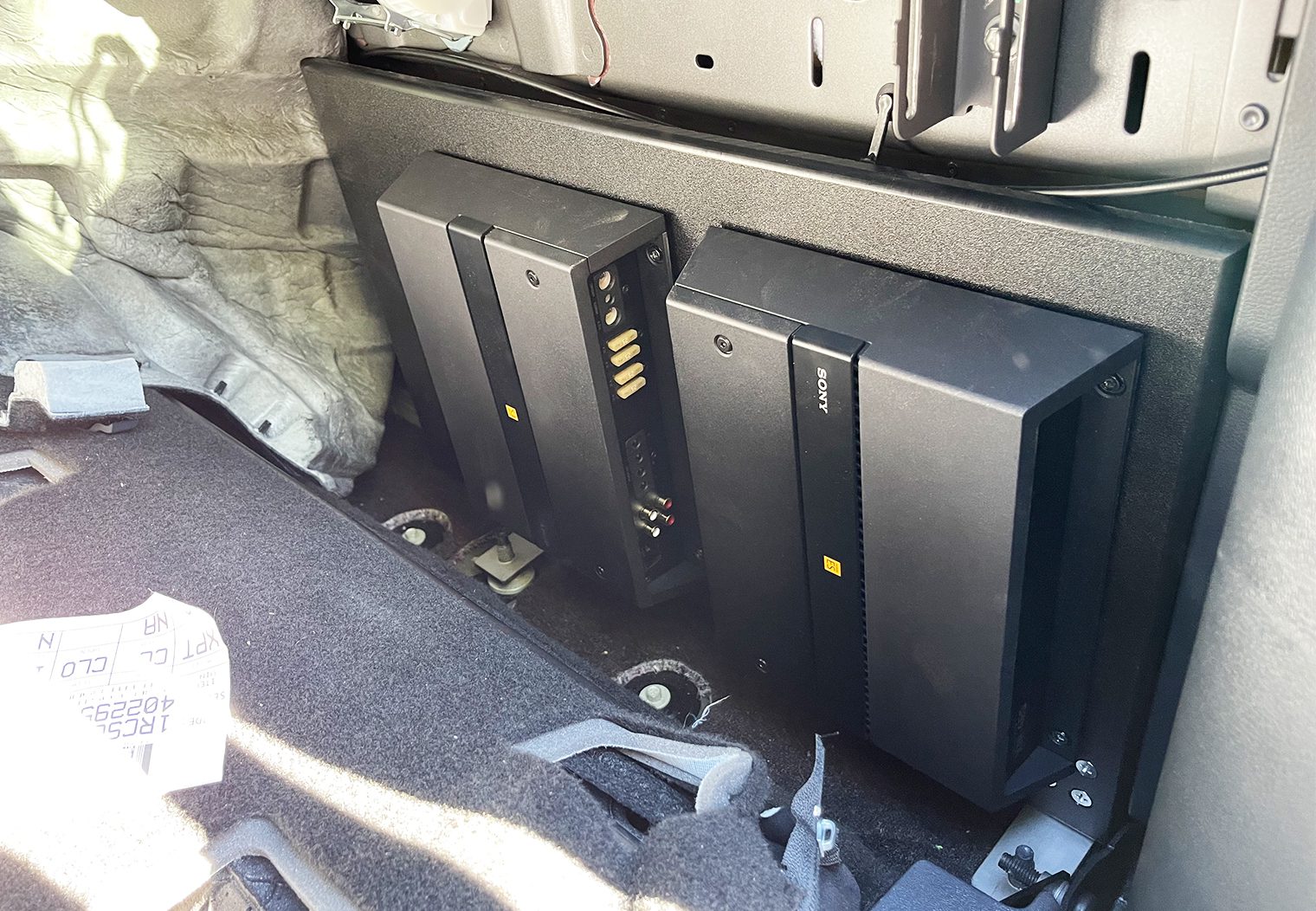
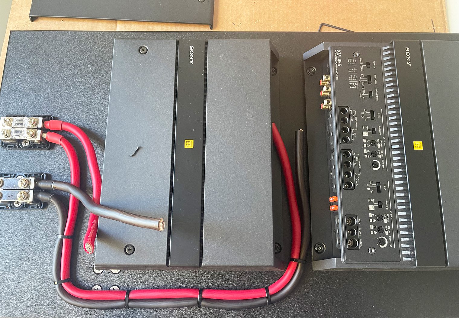
The next step in the process, after confirming that the amp rack would fit, was to begin prepping the rack with amplifiers, distribution blocks and power wire. The only thing I would need to when I went to install everything was plug in power, ground, RCAs and speaker wire.
Building the Subwoofer Enclosure
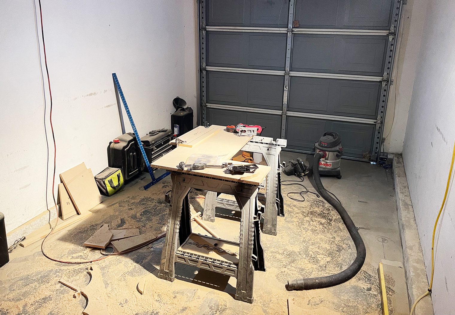
I chose to build my own subwoofer enclosure for this stereo, but there's a number of options on the market depending on what you're looking to achieve. My main reasoning behind building my own was because I wanted a sub enclosure AND storage. At the time of this build, there wasn't a sub enclosure that would also provide me with storage, and there wasn't a storage piece that had a build in sub enclosure. This was probably the most ambitious part of the project for me – I was moving and my table saw and other tools were tucked in storage so I was stuck with the basics. But I made it happen.
If you're interested in building your own box but don't have any experience doing it, I'd recommend taking a look at Crutchfield's “How to Build a Subwoofer Box” first for a high level overview to see if it's for you. I'd also spend some time checking out Mark over at CarAudioFabricators on YouTube. Lots of great content on his channel.
For those of you who aren't as ambitious but still want the fitted look under the seat, there are options for you too. I would recommend taking a look at Crutchfield's Car Subwoofers & Boxes section. Simply type in your truck info in the “See What Fits Your Vehicle” section and then chose the best option for you.

JL Audio's Stealthbox is a great example of a high-performance subwoofer enclosure that will fit perfect underneath your F-150's rear bench if you have a SuperCrew cab.
Designing the Enclosure in 3D Modeling Tool
A good enclosure starts with a good design. I had a good time with the design process for this enclosure. I used a 3D modeling too called SketchUp to design the box. I highly recommend SketchUp for these types of projects if you're a DIYer just looking for a free tool to have fun with. But it also has some great sophisticated features that take it well beyond just the DIY designer.
My design had three key requirements:
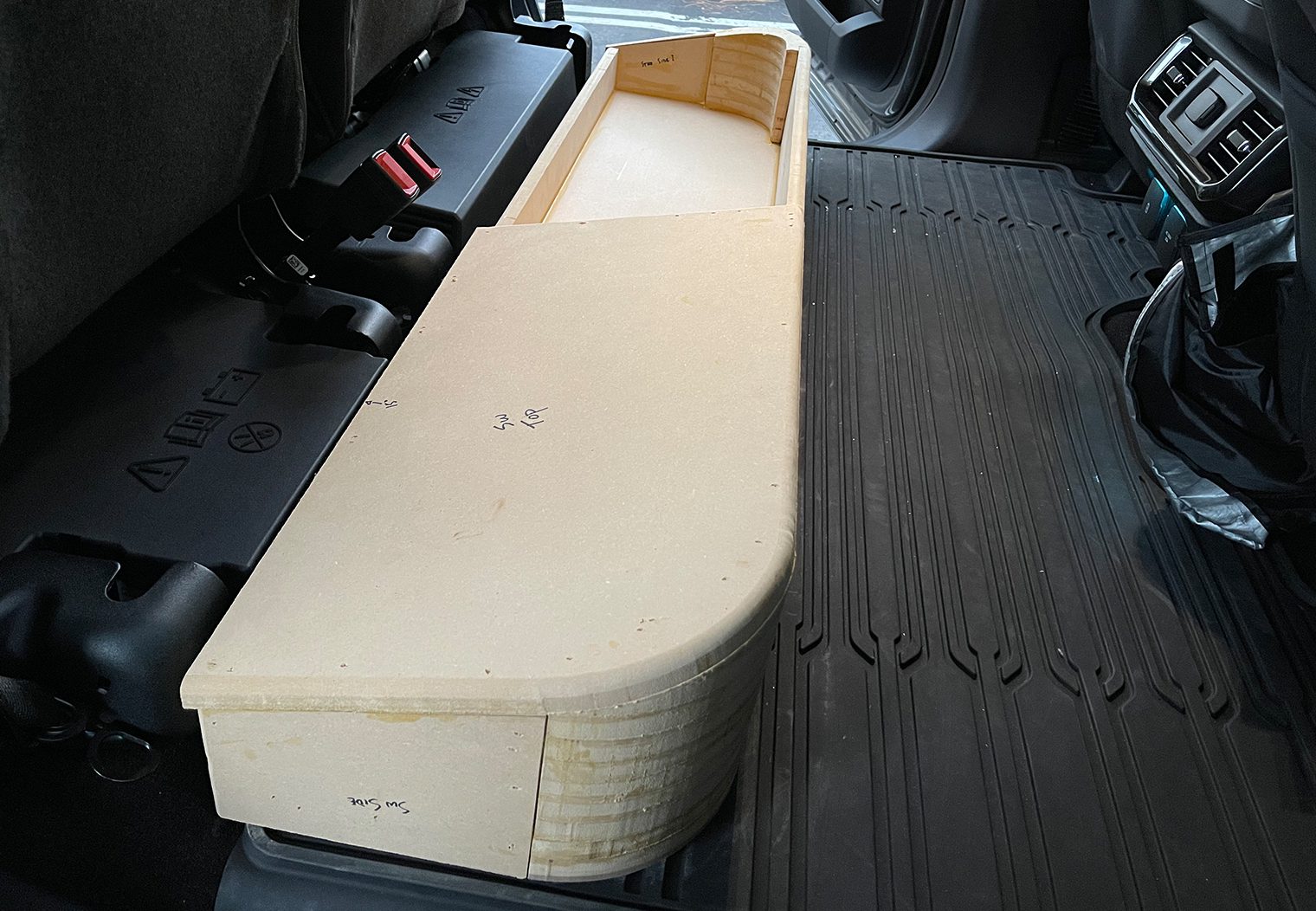
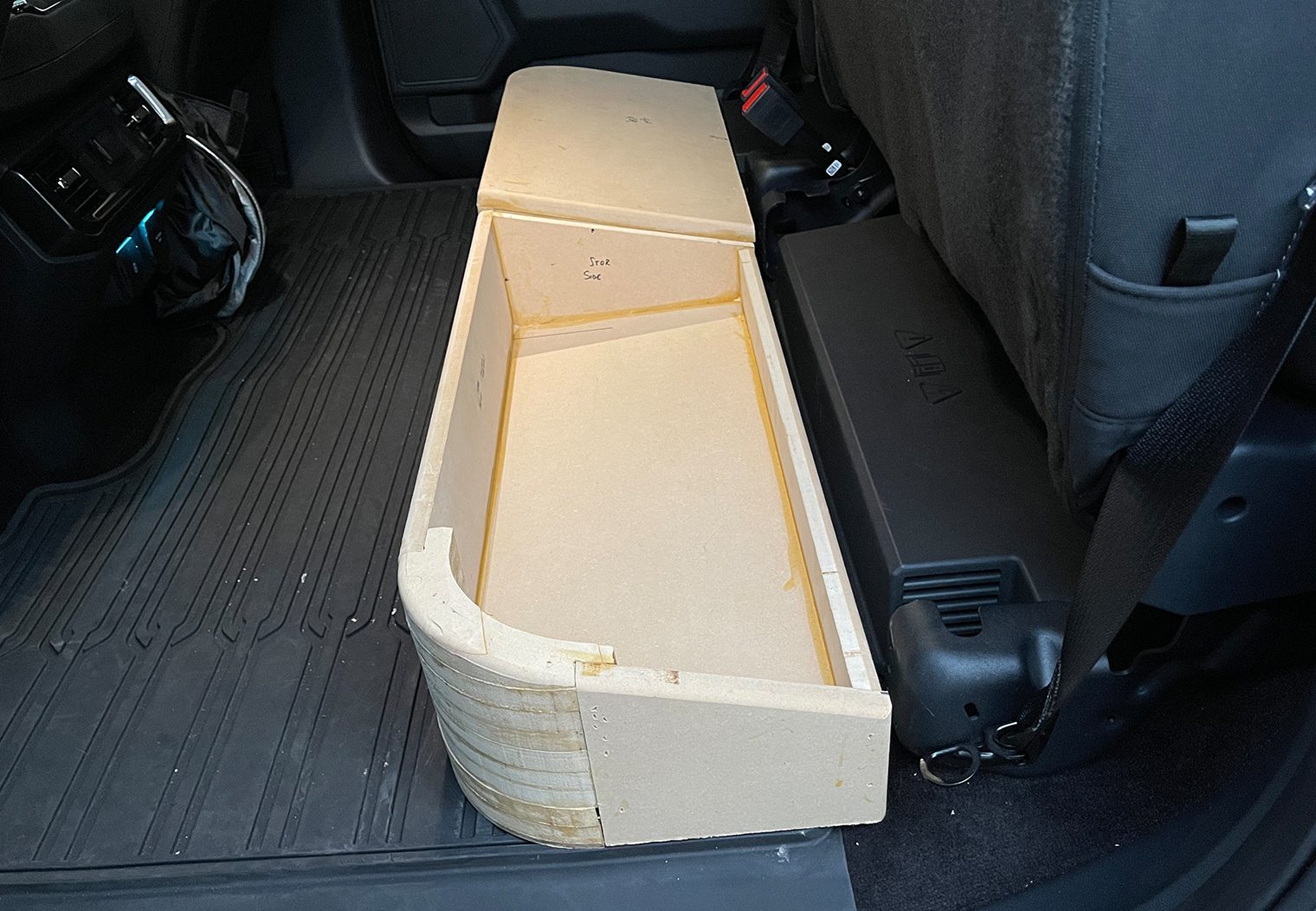
- The subwoofer enclosure had to fit underneath the single folding rear seat on the passenger side of the truck.
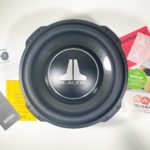
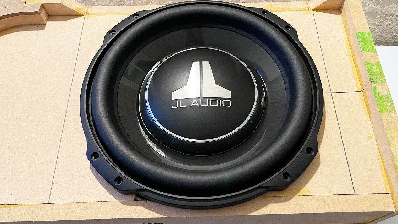
- The subwoofer enclosure needed to meet the volume specs of the JL Audio 12TW3-D4 subwoofer that I was going to use.
- The remaining space under the folding two seats on the driver side needed to be for storage.
So I took to SketchUp and designed the enclosure that met my needs.
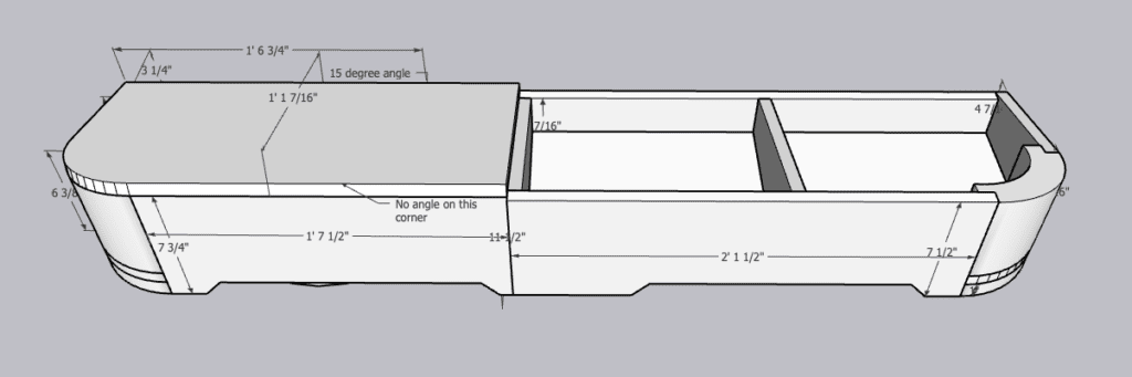
What was great about this tool too is that I could calculate the volume inside of the enclosure, ensure that the specs of the subwoofer would fit within (and wouldn't bottom out or have depth issues), and finally it would also provide me with measurements for all my cuts.
Cutting the Pieces
I purchased a single 4′ x 8′ sheet of 3/4″ MDF for the entire closure. I used probably 3/4 of that sheet (this included a couple recuts too that I measured incorrectly). For anyone out there interested in doing a build like this, my recommendation is to purchase a table saw!
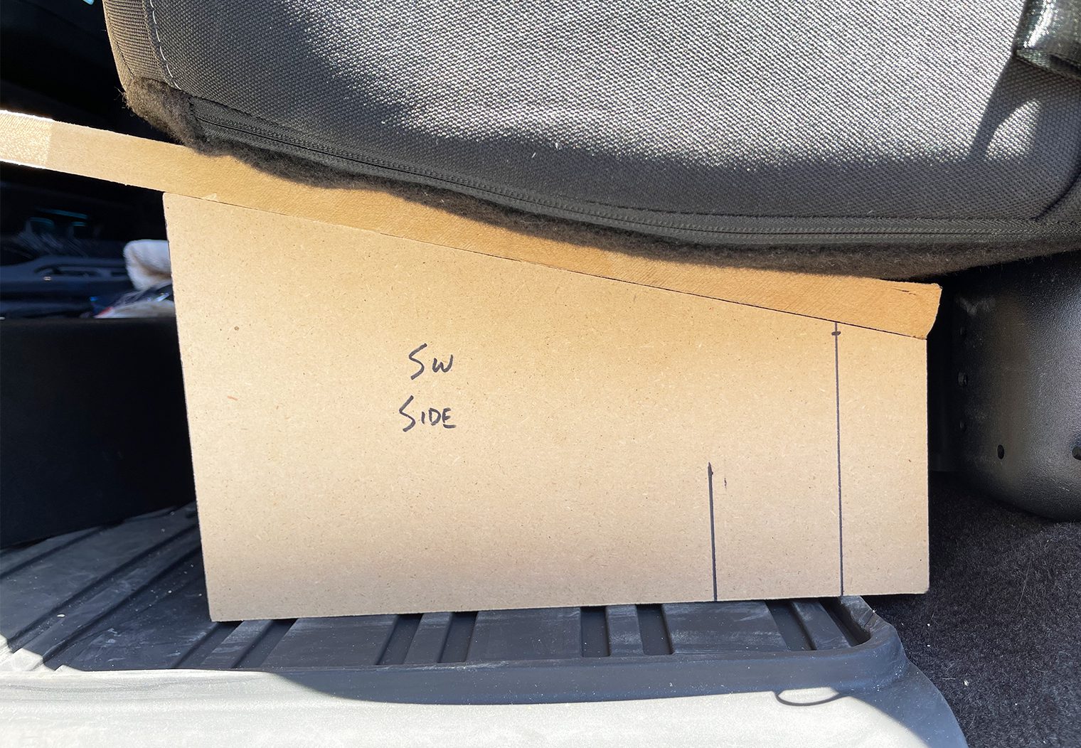
I took all of my measurements from SketchUp, printed them out and pre-cut all of the required pieces. Nothing too special to note here for the majority of the cuts – just measuring and cutting.
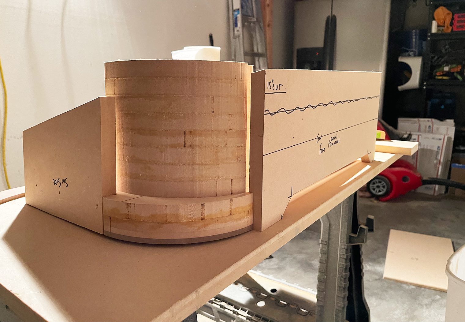
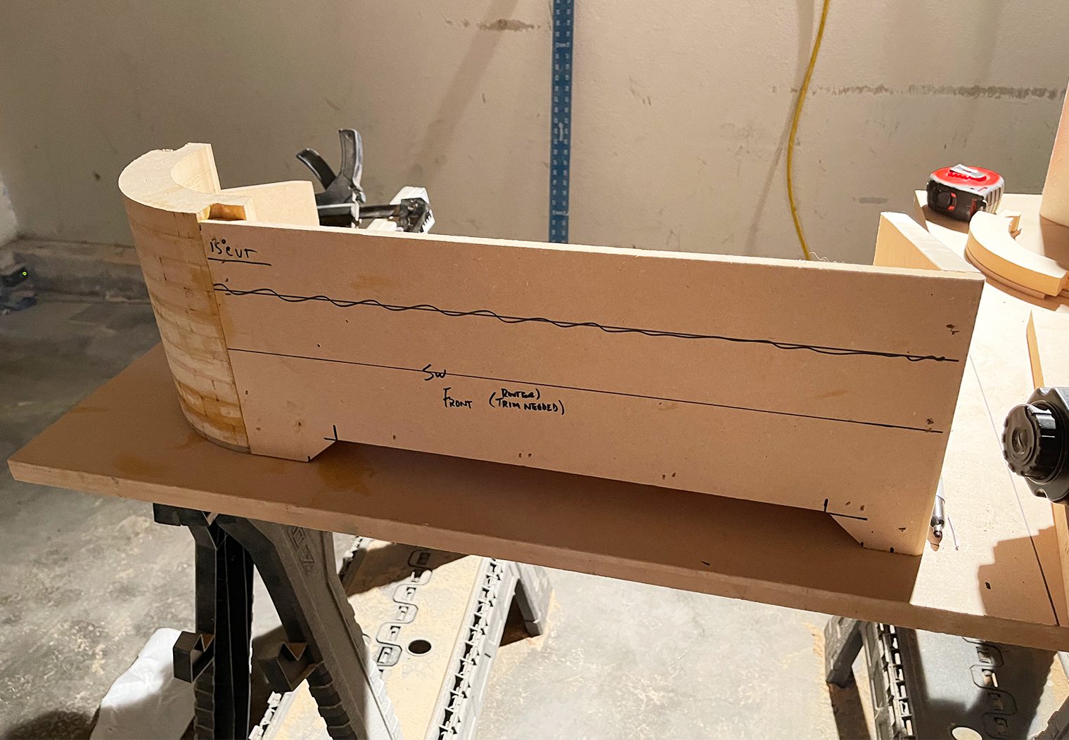
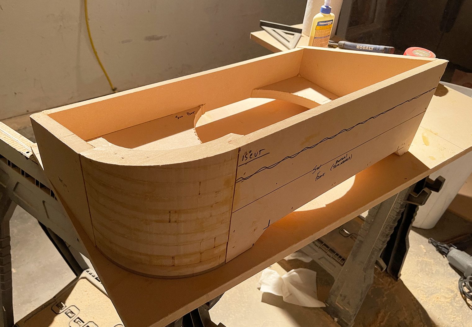
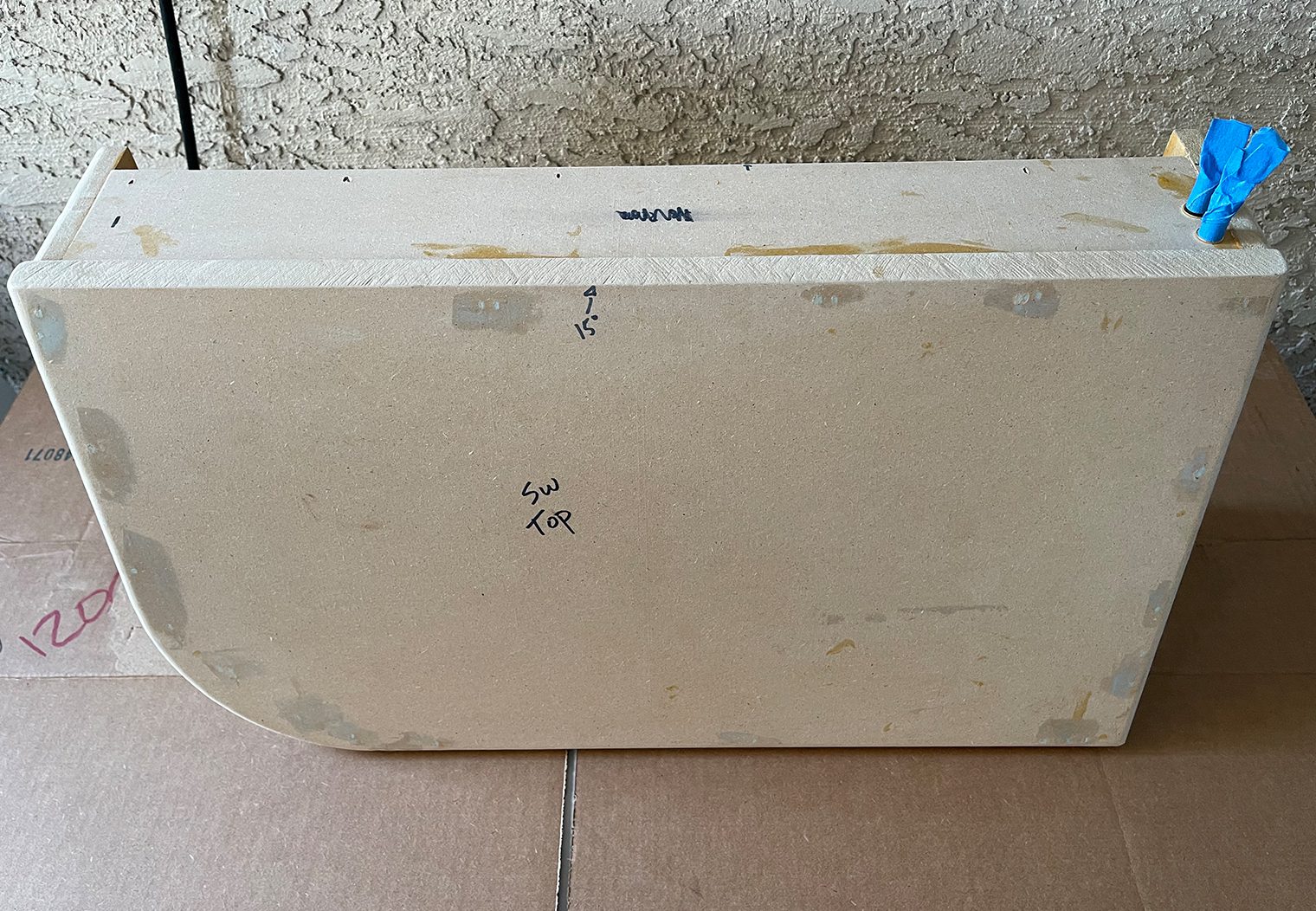
I started with the slanted cuts that would serve as the sides of my enclosure. This way, if my measurements weren't perfect, I could make tweaks before getting into the larger cuts. Everything looked good, so I continued cutting the rest of the enclosure pieces. After all the cuts were made, I used a roundover bit to round all of the key edges of the enclosure to give it a clean, finished look.
Rounded Corners and Assembly
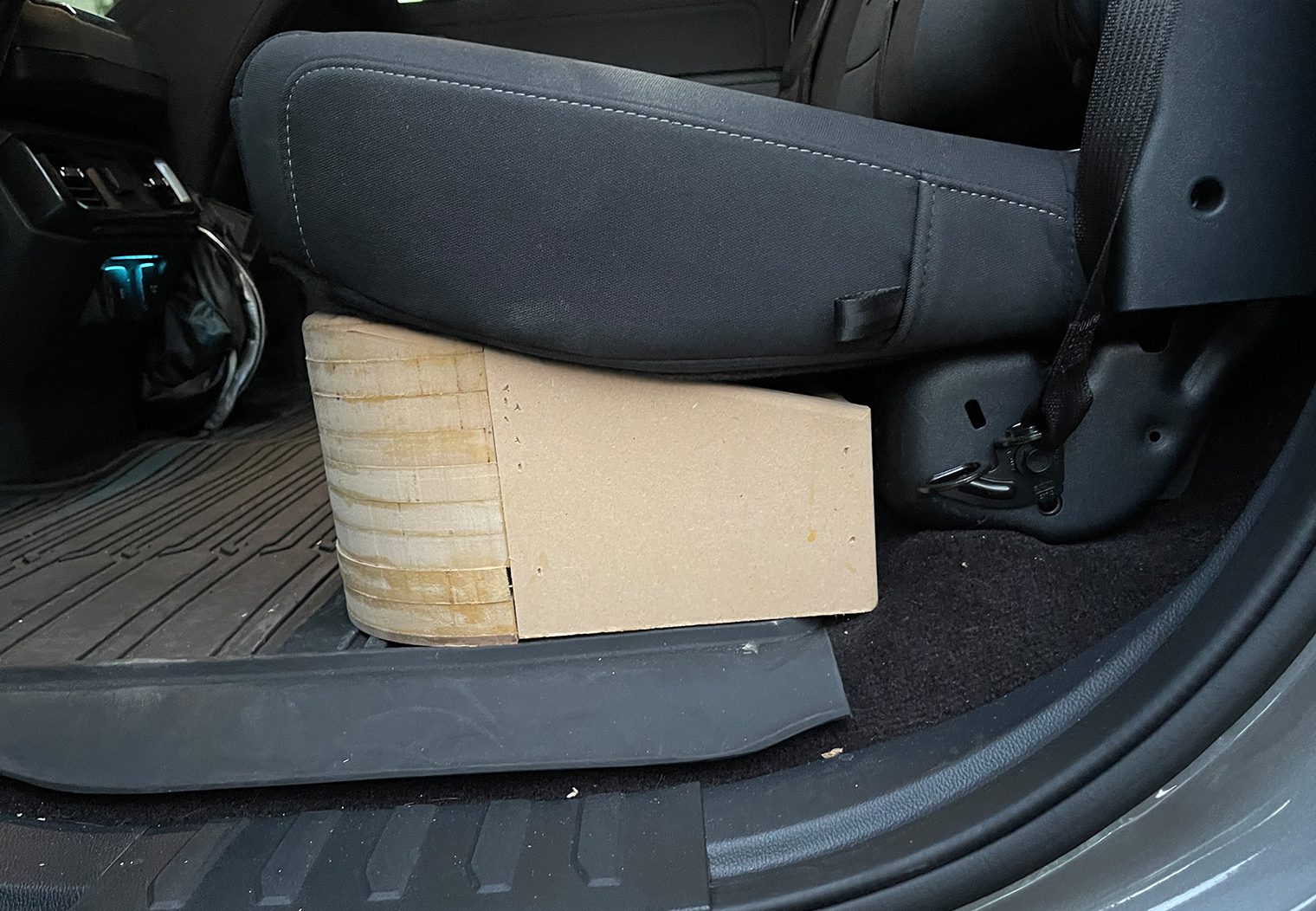
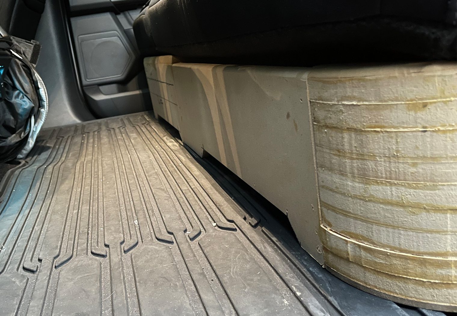
You might have noticed the rounded corners in the rendering above. These corners were meant to match the curvature of the rear seats so that I could utilize as much area without having any corners stick out from under the seats. This really brought this enclosure to another level of fit and finish and was worth the extra time. There are two ways you can go about incorporating rounded corners into the design of your box:
- Cut them yourself like I did using a router and Mobile Solutions' 5″ Smart Corner template. You can purchase the set here for around $70. I would highly recommend you have a router table if you want to do it this way. Cutting them with a standard router with a trim bit is possible, but much more difficult, less accurate and more time consuming. This was what I did and if I had the option, I would have purchased a router table to do it.
- The simple route – purchase pre-cut sets from mobile solutions. If you only plan on building one sub enclosure for one vehicle, this is the way to go. For $55 bucks you can purchase a 20 piece set that'll likely get you all the way there. You can purchase these from Mobile Solutions as well here.
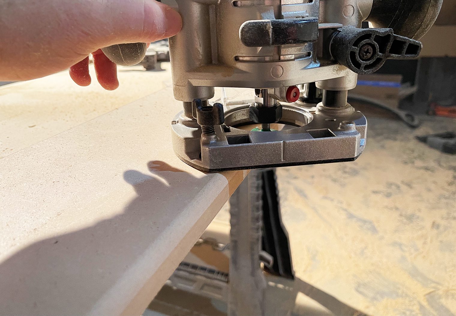
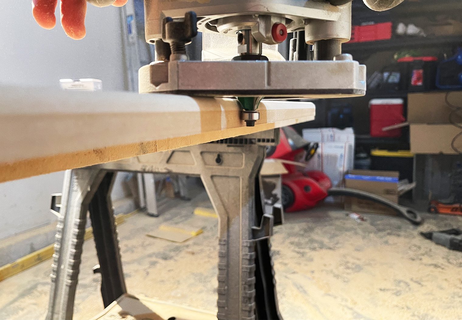
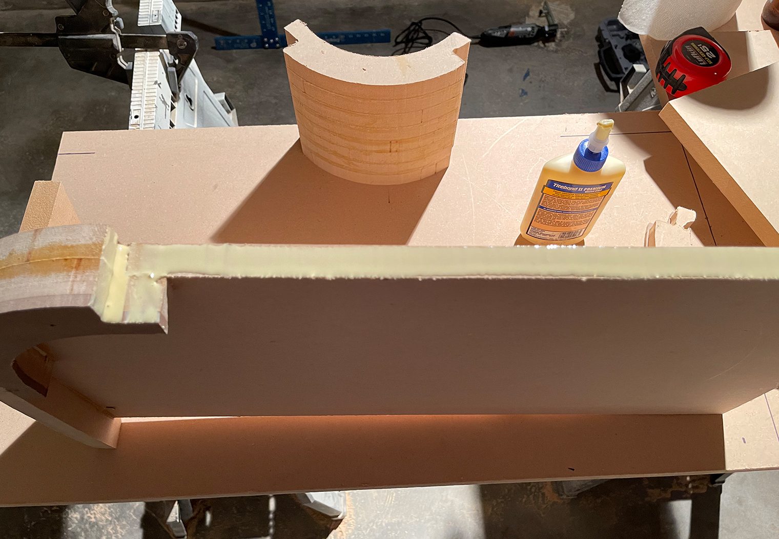
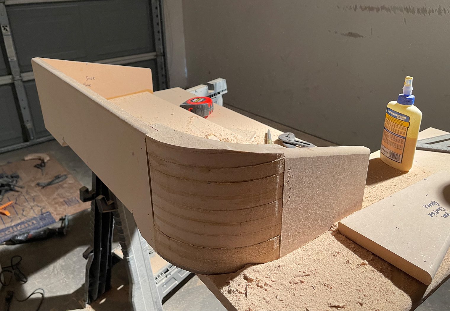
Once you either cut or receive your pre-cut pieces, these all need to be glued together and stacked at the height of the highest edge of your enclosure. Once they're stacked and your enclosure is semi-assembled, you'll have to come back and trim down the angle of the rounded edges to match the angle of the slant. Here's a few photos of how I assembled the enclosure and then trimmed down the excess round corners using my router.
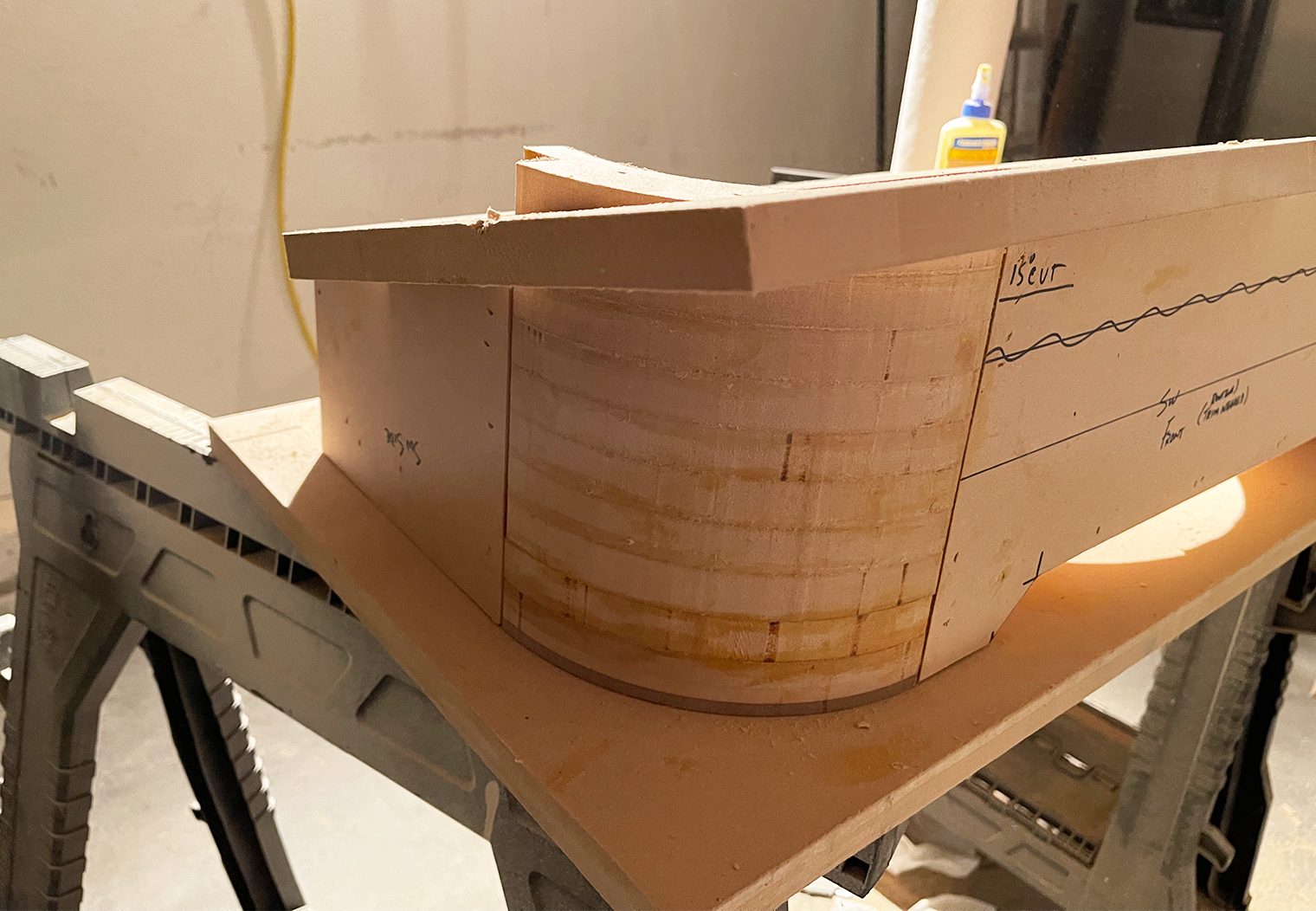
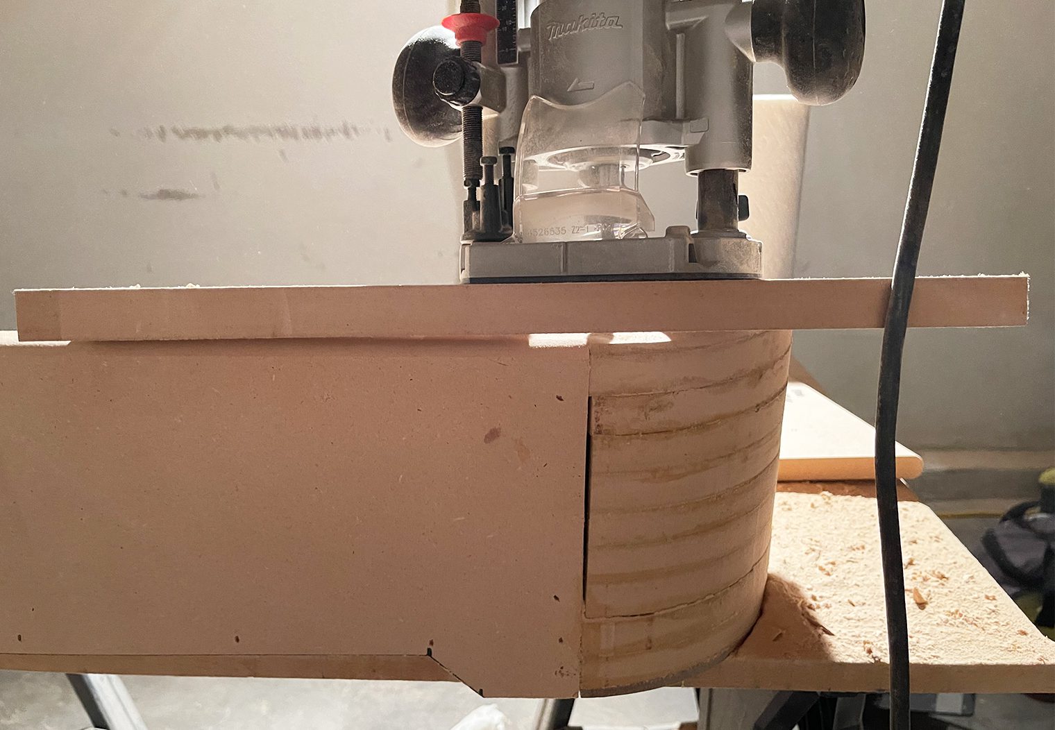
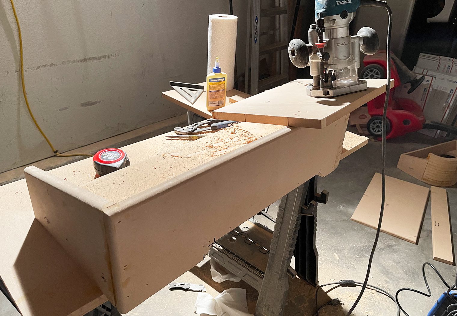
The end result came out great. The corners were cut exactly to the slanted angle of the box so I could fix the final top piece of the enclosure onto the enclosure. There was a little cleanup I needed to do before paint but overall I was pleased with the result.
After the enclosure was completed and assembled, I again checked all my measurements and did a test fit before prepping for paint. Perfect fit!
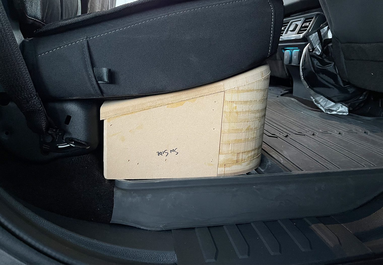
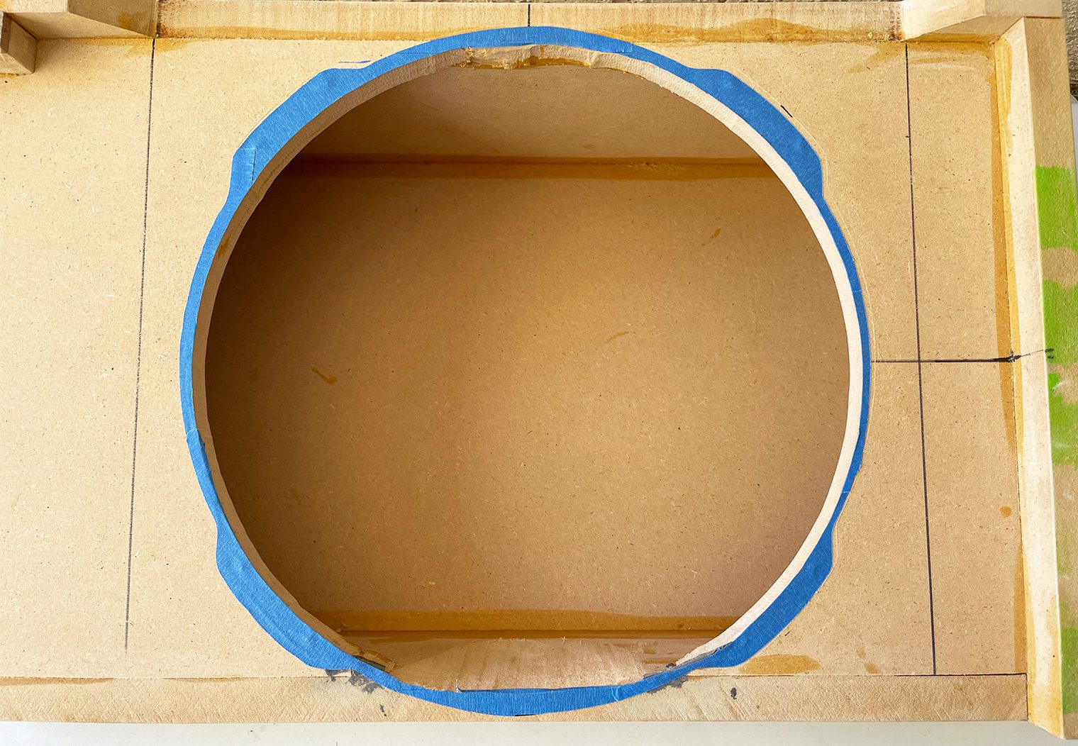
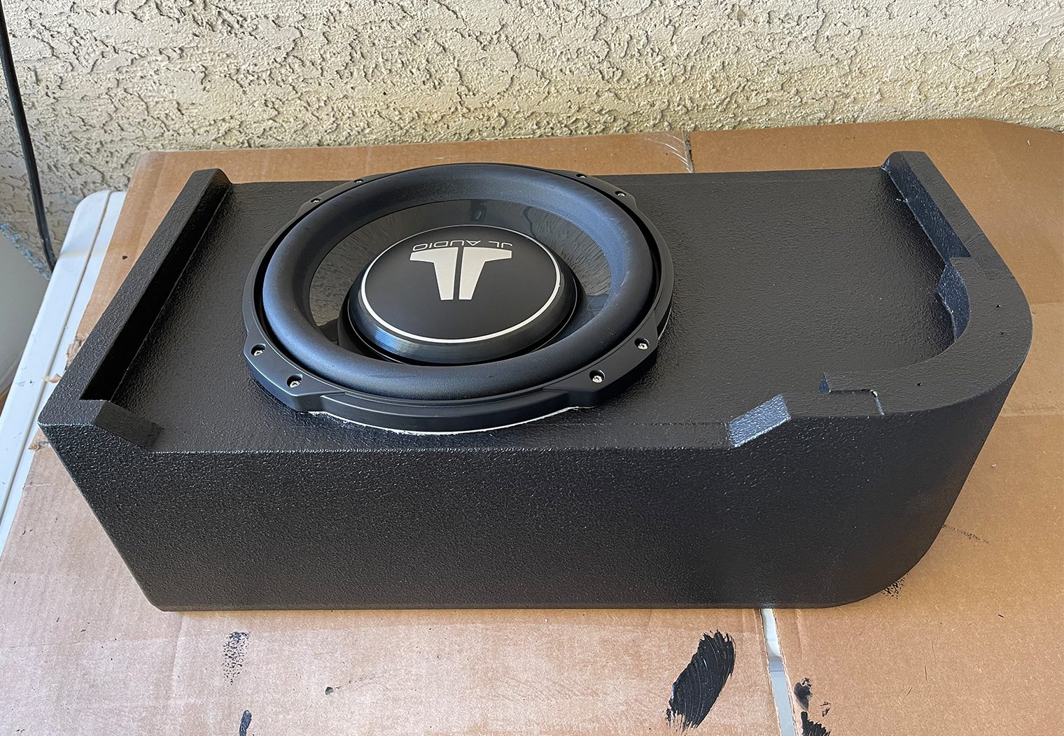
I also double checked the subwoofer fit. No problem here, although from front to back, this was a tight fit for even this subwoofer. I don't think a slim subwoofer that didn't have JL Audio's Tab Ear design would fit well in this enclosure.
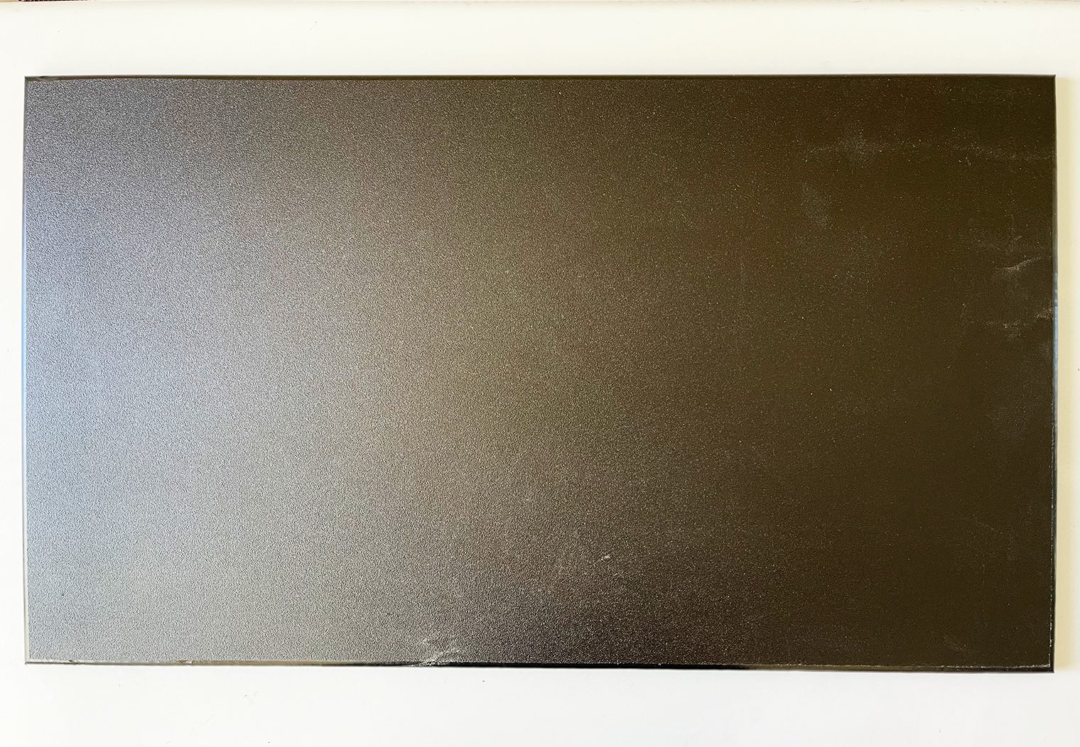
Prep & Painting the Enclosure
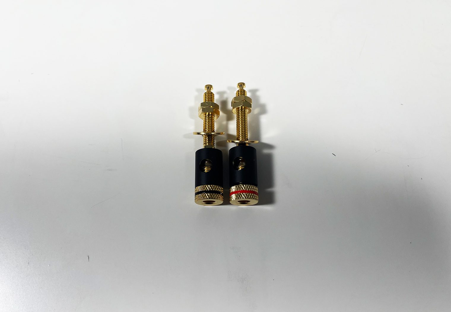
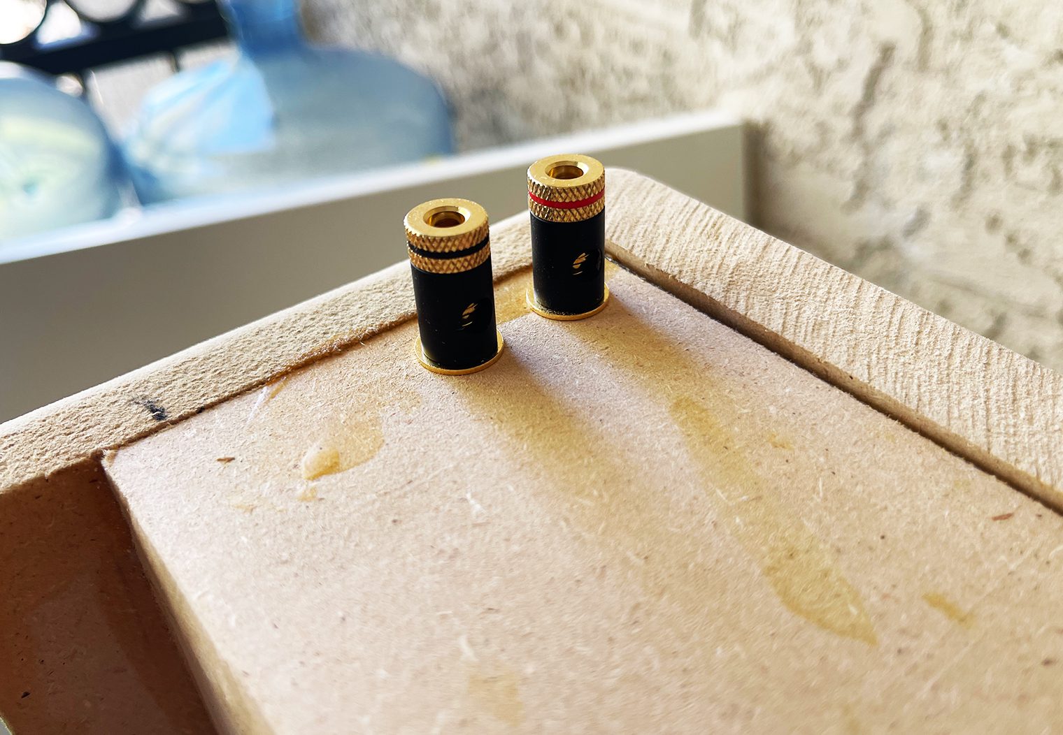
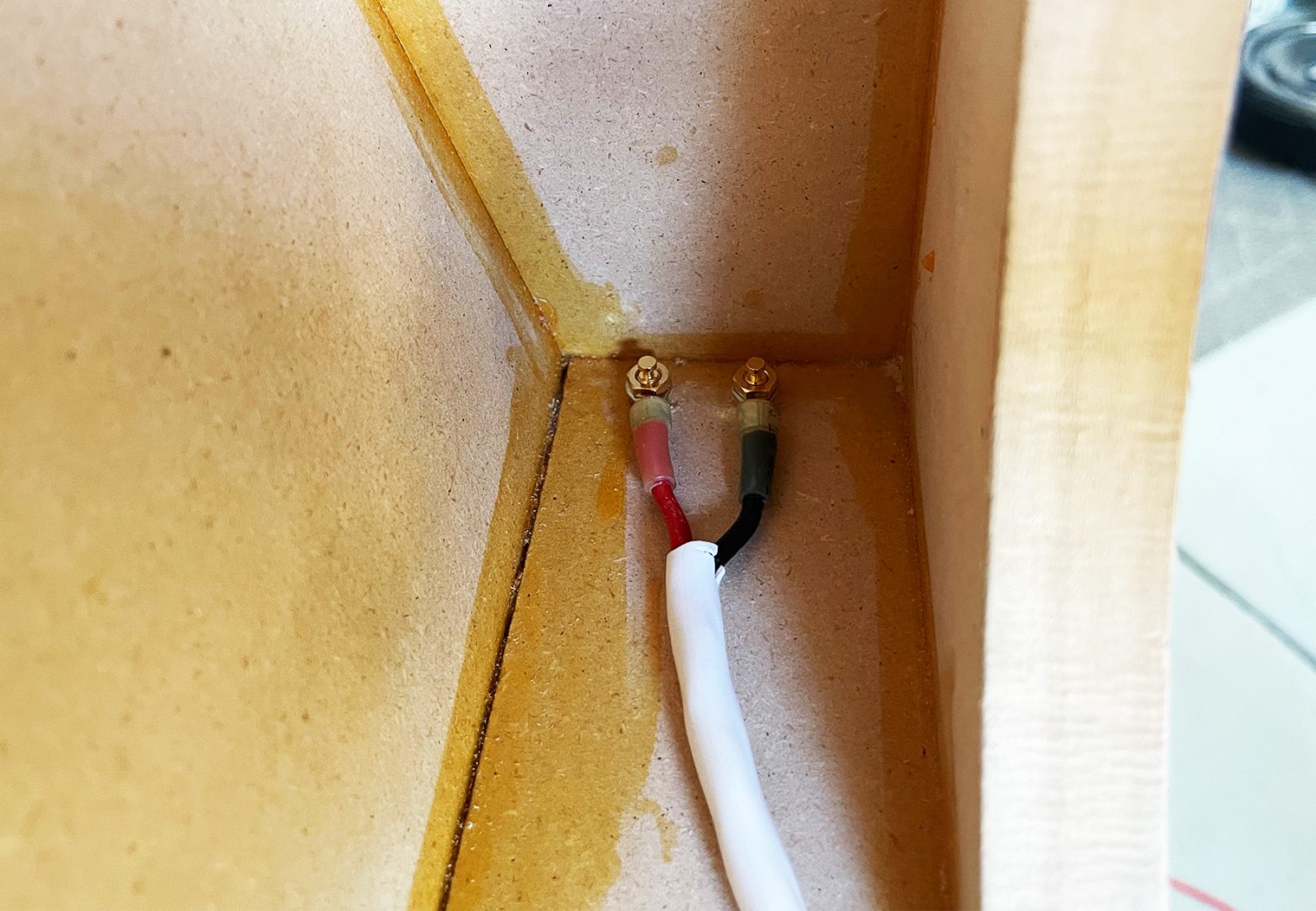
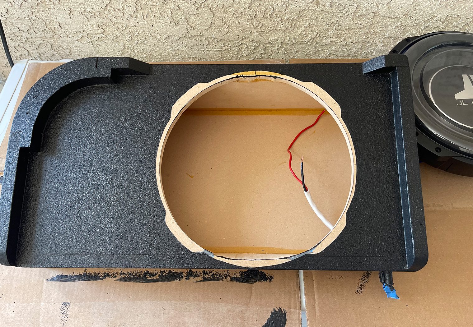
After wiring up a couple terminal posts to run wire from the outside of the box to the subwoofer on the inside, the final step for the enclosure was to prep it and paint. My rounded corners weren't perfect, so I needed to smooth them out a bit. I used some Bondo to smooth the rounded corners and also fill all of the nail holes throughout the enclosure.
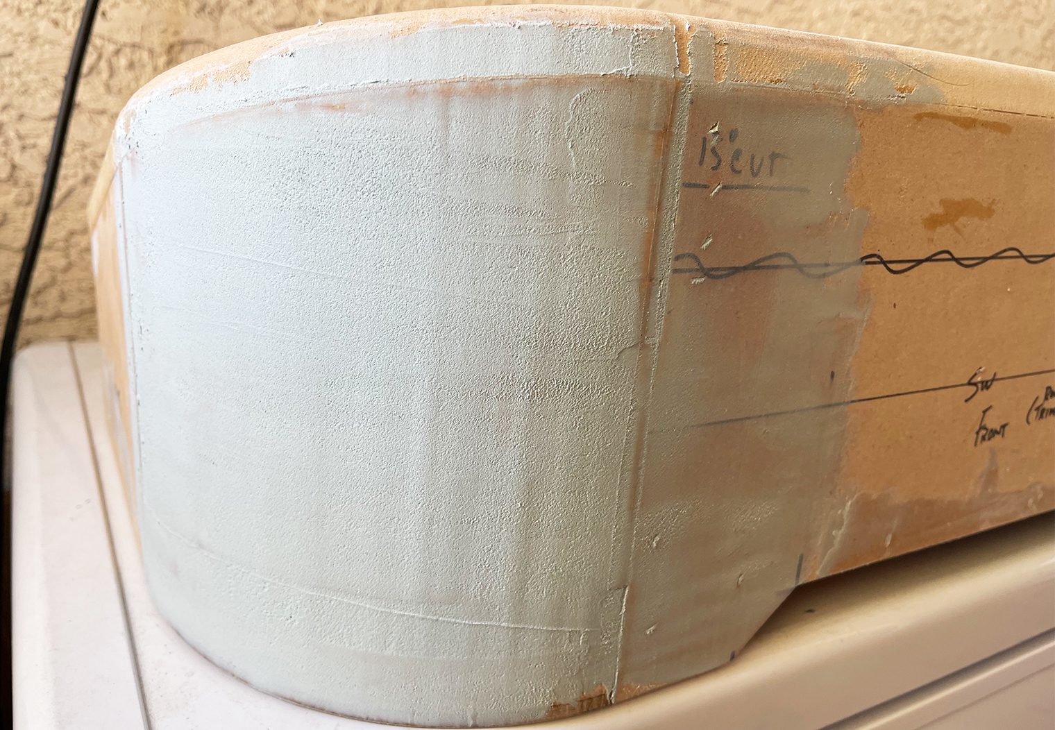
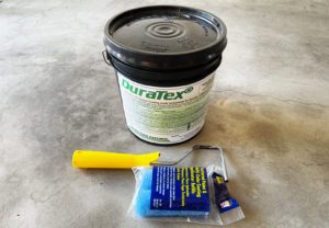
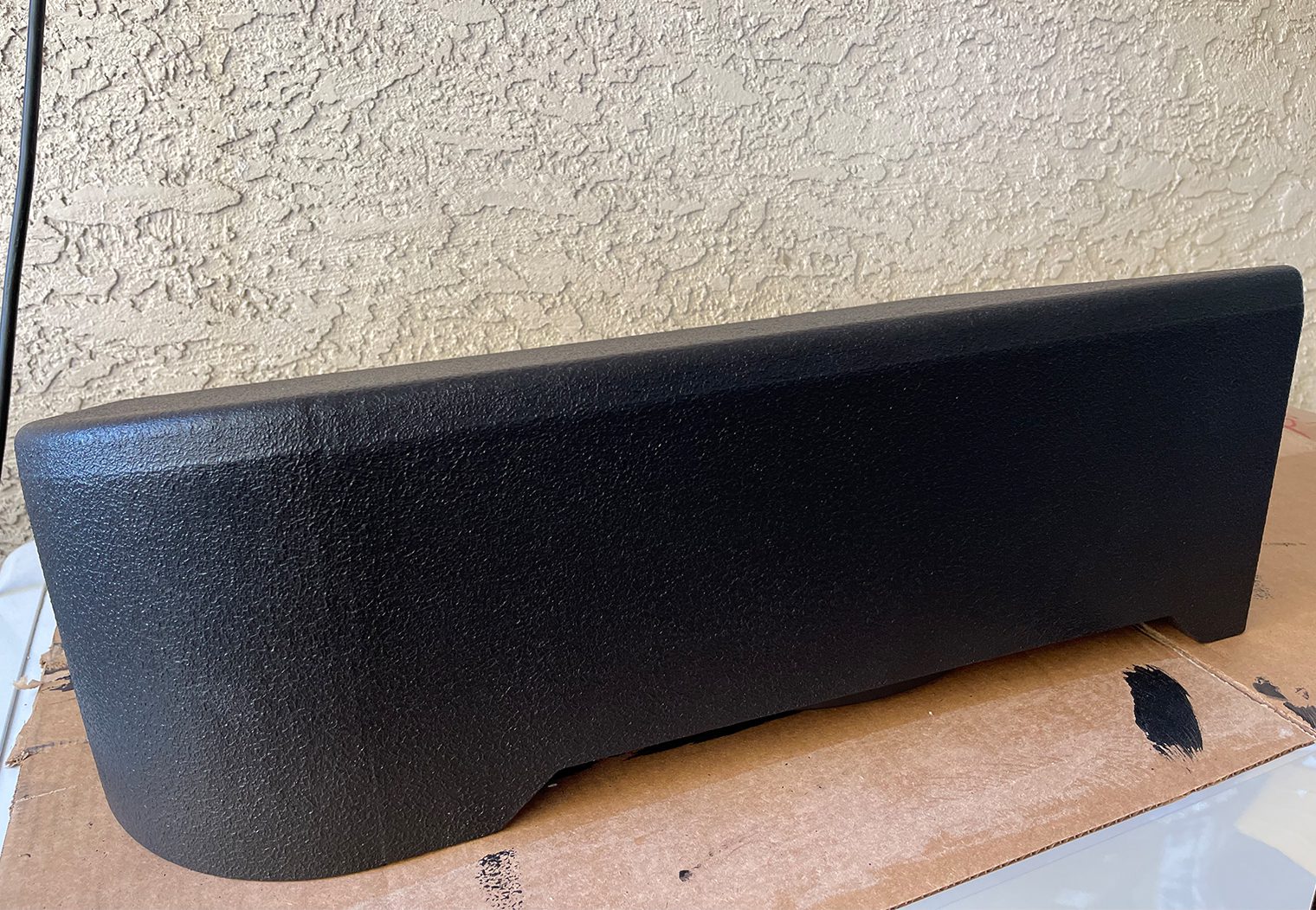
Once the enclosure was sanded, prepped and taped I was ready to go to paint. For this enclosure I used a roll-on, textured speaker enclosure paint from Acry-Tech. It's called DuraTex. It's an awesome solution for these types of enclosures where you need something that will adhere well to the surface of MDF, withstand a bit of a beating, and also look really nice. I purchased a gallon directly from Acry-Tech Coatings because I planned on using this for other subwoofer enclosures. But if you're simply painting an enclosure that's the size of mine, I would recommend the single pint from Amazon. A pint would have been enough for this enclosure and is significantly cheaper. It's also probably a Prime purchase so shipping will be quick.
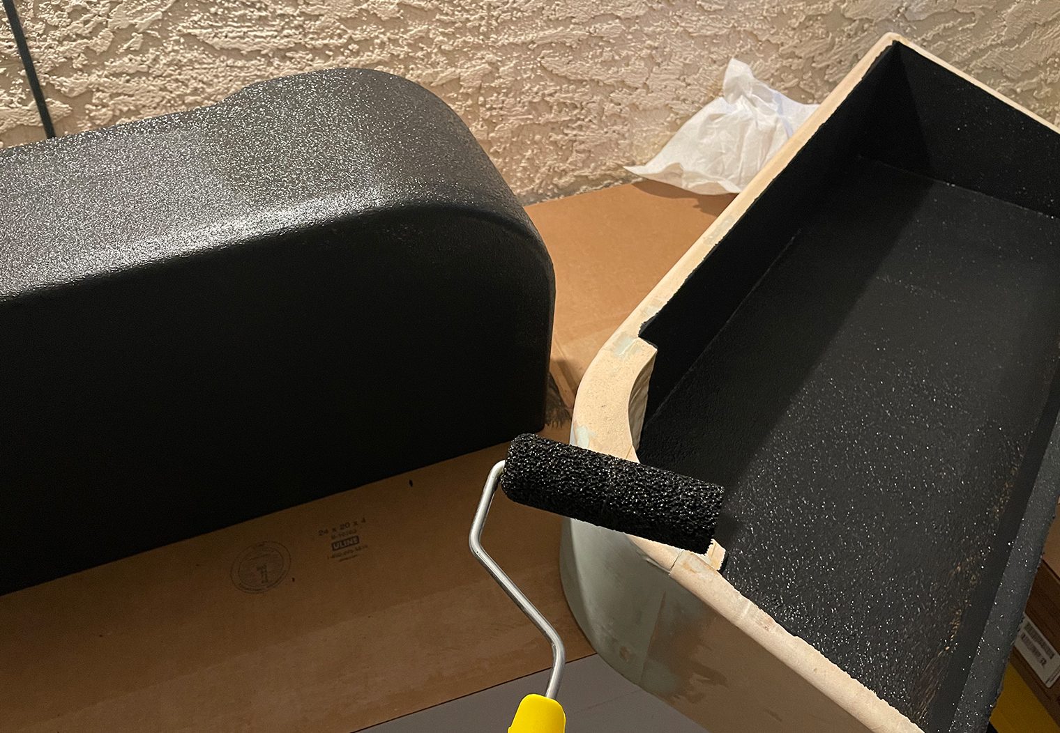
The application of DuraTex is super simple too – just roll on evenly, wait for 30 to 60 minutes before applying another coat, then let dry. I use three coats.
I really like the look of this product in the truck application like this. It's also a great alternative to having to carpet or vinyl an enclosure.
Wrapping Up
With the completion of the subwoofer, I was now officially ready to plan my day of installation! Stay tuned for the final article of this series to find out how the installation and tuning went and how the final product sounded!
Before I wrap up though, I want to give a shout out to one of the build sponsors, Crutchfield. I personally purchased a number of products from their Online Store but also used their vehicle fitment guide to figure out things like speaker sizes, wire harnesses, and even browse through things like subwoofers. If you're planning your system for your F-150, Crutchfield is a great start. Their experts are available for questions on chat or on the phone. And they always back their products up with a 60 day return policy and free lifetime tech support on the product you purchase!


Any chance you can share or sell the .stl of the tweeter bracket?
Very interested in purchasing the dual dash and tweeter mounts. Or the file to print them. Awesome work!
Thanks for your comments! We’ve created a separate product page for you to download the tweeter, fuse holder and center dash plate adapter. You can find and download these files here: https://www.caraudionow.com/shop/2021-ford-f-50-custom-tweeter-midrange-speaker-3d-print-files/
Thanks so much for the files – unfortunately there is a 403 error when trying to download them. Can these be made available again?
Should be fixed now!
That’s a great looking box!!!
Kameron is there any chance you could either post or I could purchase the drawings for the box , it’s by far the best one I’ve seen and exactly what I’d like to build for my f150 box build
Hello – great article – the link to download the stl files does not work any longer (403 error) – can the permissions be updated or re-uploaded? (I am working to redesign the dual center channel files in Tinkercad myself in the meantime)